TP-6881 7/15102 Section 5 Component Testing and Adjustment
5.14.1 Fuel Selector Valve Adjustment
Screw
The fuel system is factory-adjusted to comply with
applicable emission standards and to provide the best
possible hot and cold starting. If the fuel selector valve
requires adjustment, obtain a new fuel selector valve to
replace the factory-installed valve. See Figure 5-28 for
the fuel selector valve location. Refer to the generator
set Parts Catalog for the fuel selector valve part number.
Note: Adjusting the factory-installed fuel selector
valves on emissions-certified generator sets will
void the emission certification. Do not change the
adjustment screw setting.
1. Adjustment screw (Do not adjust!)
tp6879
1
Figure 5-33 Valve Positions
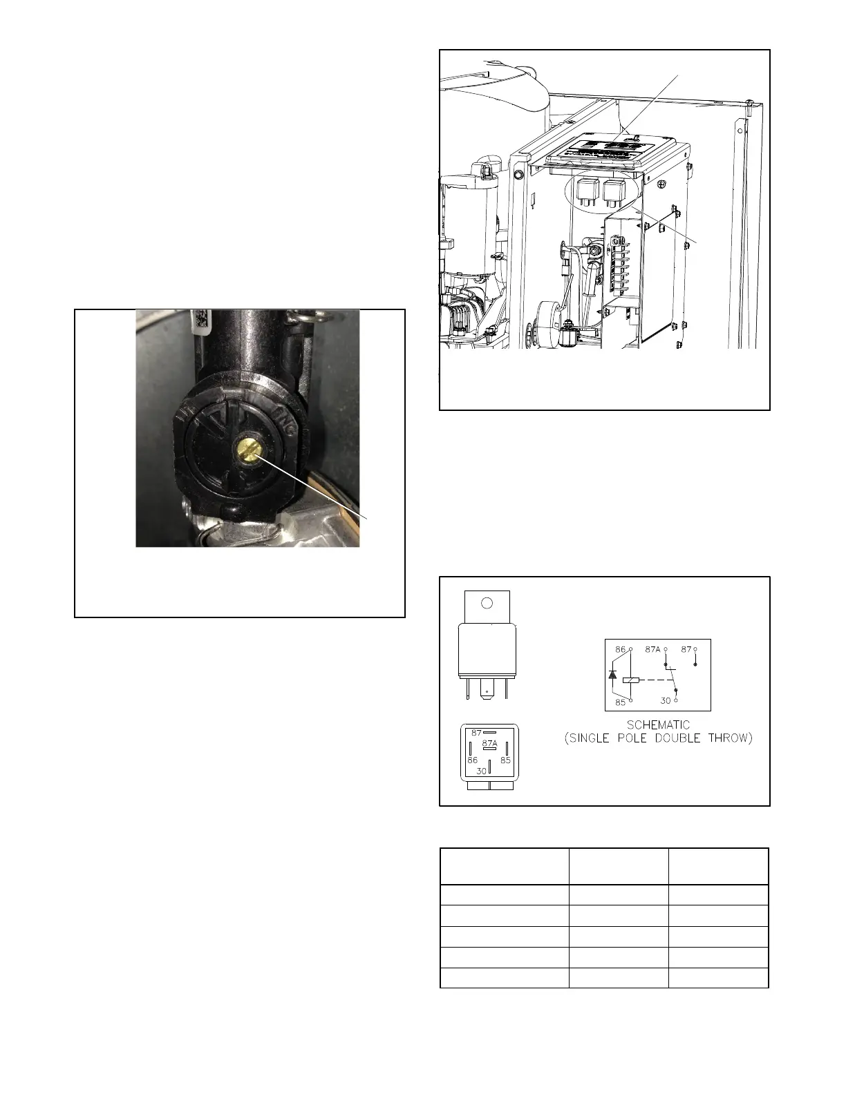
5.15 Starter and Run Relay
The starter relay (P10) and the r un relay ( P11) are
located underneath the controller inside the junction
box. To access the relays, remove the two controller
screws and lift the controller out of the junction box.
Check for lead 71 to determine which relay is the starter
relay. See Figure 5-34.
TP-6881
2
1
1. Controller
2. Starter relay and run relay (P10 and P11)
Figure 5-34 Starter Relay Location
The starter and run relays contains an internal diode
across the r elay coil. See Figure 5-35. Continuity
checks across the coil terminals will show continuity
(low resistance) in one direction and an open circuit in
the other.
Figure 5-36 s hows the relay connections.
GM49746 259391
Figure 5-35 Starter Relay
Relay Terminal
Starter Relay
Lead
Run Relay
Lead
30 P1 P2
85 N3 N4
86 71 70
87 N/C N/C
87A 71A 70A
Figure 5-36 Starter Relay Connections

 Loading...