TP-6881 7/15 107Section 6 Disassembly/Reassembly
6.2 Disassembly
The disassembly procedure explains how to
disassemble the generator set enclosure and other
parts in order to access the alternator and engine for
service. The procedure provides important information
to minimize disassembly time and indicates where
special configurations exist which may require taking
notes.
Removing the e nclosure
Remove the generator set enclosure as described in the
following steps. See Figure 6-1.
1. Open the enclosure roof.
2. Press the OFF button on the controller.
Important: Do not allow the roof to hang from the
hinge in an overextended or unsupported position.
Without support from the piston, the weight of the roof
will damage the sheet metal. Get assistance to hold the
roof while removing the hinge bolts.
3. To remove the roof:
a. Raise the enclosure roof and use a screwdriver
to slide the retaining ring off the support piston.
b. Disconnect the roof support piston.
c. With assistance to support the roof, remove the
hinge bolts and then remove the roof.
4. Remove the two left-side or air-intake-panel
screws and pull the left side panel up and off.
5. Remove the two right-side or exhaust-panel
screws and pull the right side panel up and off.
6. Remove the wing nut and bolt holding the front
panel to the bulkhead and pull the front panel up
and off.
7. To remove the rear panel:
a. Open the junction box access panel.
Disconnect any external leads that enter the
junction box through the hole in the rear panel.
Pull the leads and conduit through the rear
panel.
b. Remove the five hexhead screws on the rear
panel and then lift and remove the rear panel.
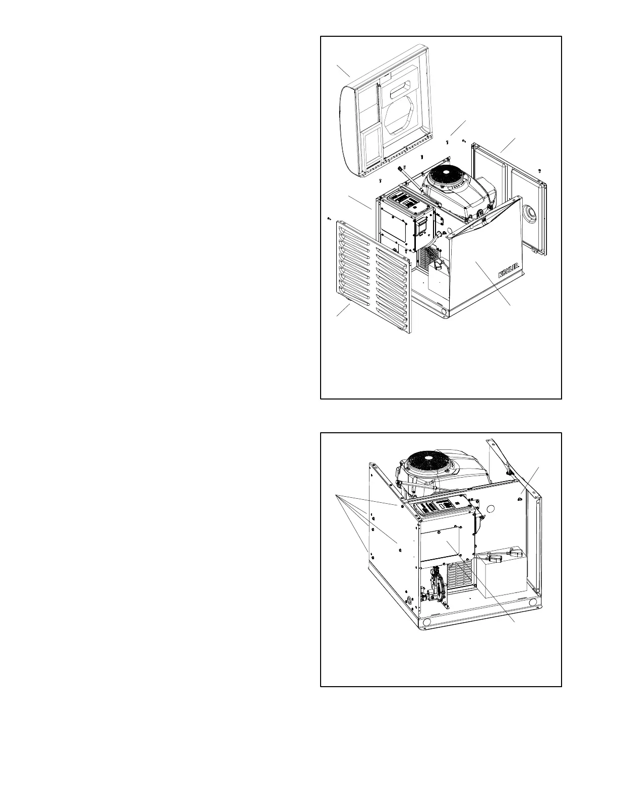
1. Roof
2. Hinge bolts (qty. 4)
3. Right side panel (exhaust end)
4. Front panel
5. Left side panel (air intake end)
6. Rear panel
1
5
4
3
6
2
Figure 6-1 Enclosure
1
2
1. Rear panel hex head screws (qty. 5)
2. Front panel wingnut
3. Junction box access panel
3
Figure 6-2 Front and Rear Panels

 Loading...