TP-6881 7/1578 Section 5 Component Testing and Adjustment
Separate Excitation Procedure
Perform the following procedure to use an external
voltage source to excite the main field (rotor).
1. Disconnect the black FN and FP leads from the
alternator at the brush holder terminals.
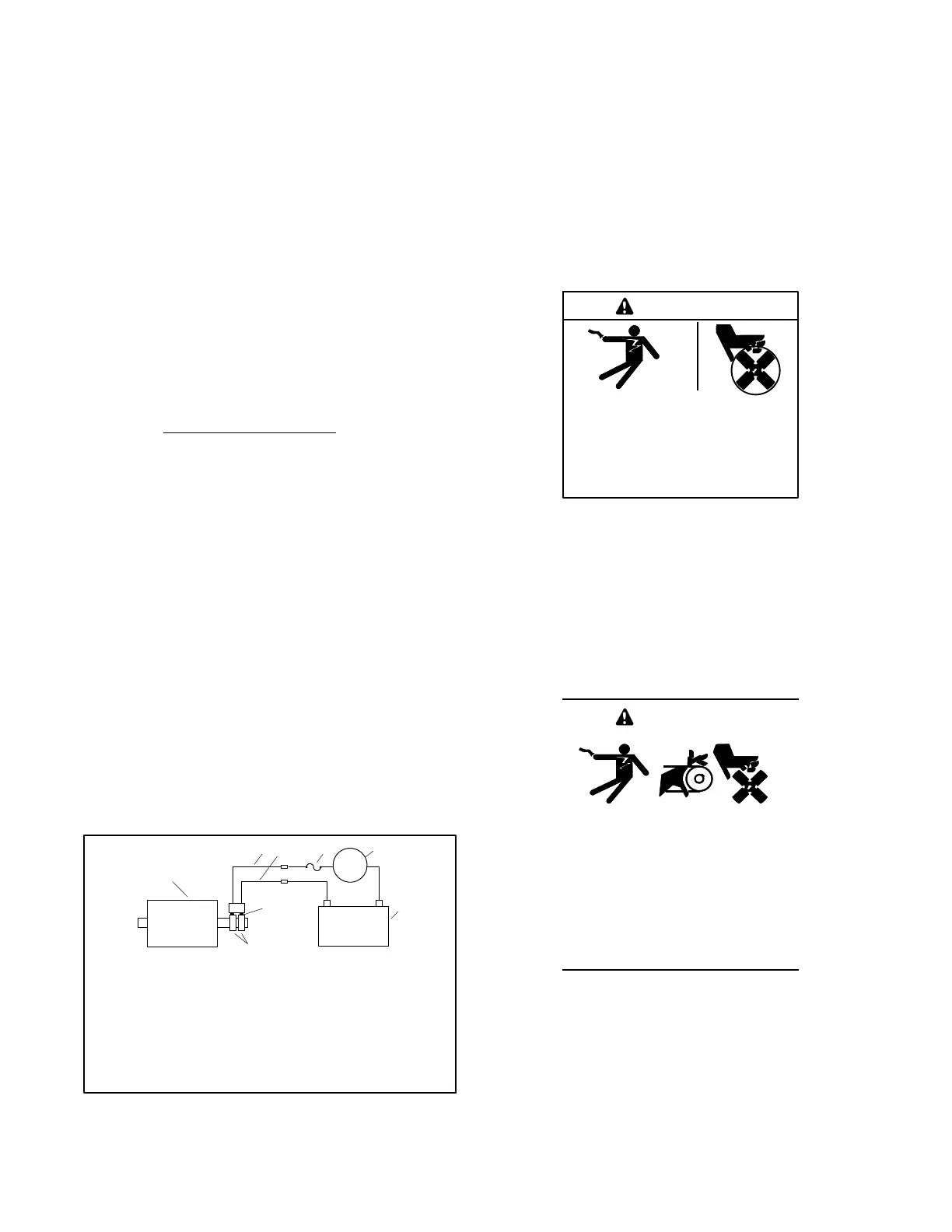
2. Connect a DC ammeter, 10-amp fuse, and a
12-volt automotive battery to the positive (FP) and
negative (FN) brush leads as shown in Figure 5-3.
Note and record the ammeter reading.
Note: The approximate ammeter reading should
be the battery voltage divided by the
specified rotor resistance. See Section 1,
Specifications, for specified rotor resistance
values.
Example:
12 volts (battery voltage)
4 ohms (rotor resistance)
=
3amps
(rotor current)
3. Start the engine and check that the ammeter
reading remains stable. An increasing meter
reading indicates a shorted rotor. A meter reading
decreasing to zero or an unstable r eading
suggests a running open. Refer to Section 5.5,
Main Field (Rotor), to test the rotor. If the ammeter
reading is stable, proceed to step 4.
4. Check for AC output across the stator leads; see
Section 5.4, Stator. Compare the readings to the
AC output values shown in Section 1,
Specifications. If the readings vary considerably, a
faulty stator is likely. Refer to Section 5.4, Stator,
for further information.
5. If this test shows that the rotor and stator are in
good condition, check the wiring and fuses. Check
the controller settings and connections. See
Section 3, C ontroller.
+
+
1
2
3
4
5
6
7
8
-
1. FN lead disconnected in step 1
2. FP lead disconnected in step 1
3. 10-amp fuse
4. DC ammeter
5. 12V battery
6. Brushes
7. Slip rings
8. Main field (rotor)
FP
FN
-
Figure 5-3 Separate Excitation Connections
5.4 Stator
The stator contains a series of coils of wire laid in a
laminated steel frame. The stator leads supply AC
voltage to the load and voltage regulator. Before testing
the stator, inspect it for heat discoloration and visible
damage to housing lead wires, exposed coil windings,
and exposed areas of frame laminations. Be sure the
stator is securely fastened to the stator housing.
Note: Disconnect all stator leads before performing all
stator tests.
Hazardous voltage.
Can cause severe injury or death.
Operate the generator set only when
all guards and electrical enclosures
areinplace.
Moving parts.
WARNING
High voltage test. Hazardous voltage can cause severe
injury or death. Follow the instructions of the test equipment
manufacturer when performing high-voltage tests on the rotor
or stator. An improper test procedure can damage equipment
or lead to generator set failure.
Short circuits. Hazardous voltage/current can cause
severe injury or death. Short circuits can cause bodily injury
and/or equipment damage. Do not contact electrical
connections with tools or jewelry while making adjustments or
repairs. Remove all jewelry before servicing the equipment.
Accidental starting.
Can cause severe injury or death.
Disconnect the battery cables before
working on the generator set.
Remove the negative (--) lead first
when disconnecting the battery.
Reconnect the negative (--) lead last
when reconnecting the battery.
WARNING
Disabling the generator set. Accidental starting can
cause severe injury or death. Before working on the
generator set or equipment connected to the set, disable the
generator set as follows: (1) Press the generator set off/reset
button to shut down the generator set. (2) Disconnect the
power to the battery charger, if equipped. (3) Remove the
battery cables, negative (--) lead first. Reconnect the negative
(--) lead last when reconnecting the battery. Follow these
precautions to prevent the starting of the generator set by the
remote start/stop switch.

 Loading...