20-130
PC58UU-3
b
TESTING AND ADJUSTING
RESETTING PROCEDURE OF ELECTRIC SYSTEM
AND CHECK OF ITS OPERATION
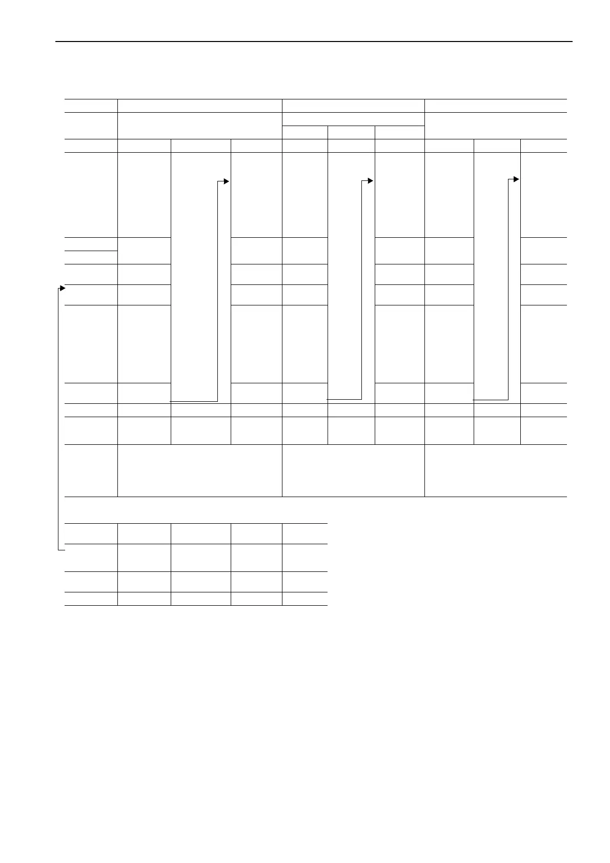
TABLE OF PROCEDURES FOR RESETTING ELECTRIC SYSTEM
Order 1 2 3
Reset Item
Initial setting at stroke end of cylinder
Prevention of interference
Setting of displayed depth to 0
Step Front — Side
Engine Running — — Running — — Running — —
Position of
work equip-
ment
(Position 1)
• Set boom to
RAISE end.
• Set offset
boom to
RIGHT end.
• Set arm to IN
end.
Caution: When
setting "Position
1", turn ON
emergency work
equpipment
operation
switch.
(Position 2)
• Set offset
boom to
LEFT end.
• Set arm to
OUT end.
!
Boom may
be at any
position.
Set bucket
to auto-
matic stop
position
(Front)
(Including
operation of
emergency
work equip-
ment opera-
tion switch)
Set the bucket
to automatic
stop position
(Side) (Includ-
ing operation
of emer-
gency work
equipment
operation
switch
(Position 1)
• Set bucket
to DUMP
position
(Set bucket
top verti-
cally)
(Position 1)
• Set arm to
IN position
(Set bucket
top verti-
cally)
Engine
Running Running Running Running Running Running
Starting switch
Mode selector
switch position
Set displayed
depth to 0
Set displayed
depth to 0
✩ 1 ✩ 1 ✩ 2 ✩ 2
Connection of
connectors
b
+
cb
+
db
+
cb
+
db
+
cb
+
d
Method of dis-
playing and
resetting mon-
itor panel
After 2 sec-
onds, electric
system caution
lamp ([--] at
center of [88])
starts blinking
at intervals of
0.8 seconds.
After 2 sec-
onds, electric
system cau-
tion lamp ([--]
at center of
[88]) starts
blinking at
intervals of 0.8
seconds.
After 2 sec-
onds, elec-
tric system
caution
lamp ([--] at
center of
[88]) starts
blinking at
intervals of
1 second.
After 2 sec-
onds, electric
system cau-
tion lamp ([--]
at center of
[88]) starts
blinking at
intervals of
0.8 seconds.
After 2 sec-
onds, electric
system cau-
tion lamp ([--]
at center of
[88]) starts
blinking at
intervals of
0.8 seconds.
After 2 sec-
onds, elec-
tric system
caution lamp
([--] at cen-
ter of [88])
starts blink-
ing at inter-
vals of 0.8
seconds.
Disconnection
of connectors
b
+
cb
+
db
+
cb
+
db
+
cb
+
d
Starting switch — — OFF — — OFF — — OFF
Starting switch — —
ON
Resetting is
completed
——
ON
Resetting is
completed
——
ON
Resetting is
completed
Method of
checking reset-
ting
• Electronic cushion
1) Movement of boom to RAISE end
2) Movement of arm to IN end
3) Movement of offset to LEFT end
• Run the engine at full throttle and stop
work equipment automatically and
measure stopping distance (front, side).
• Lower bucket to ground with its top to
perpendicular to ground and check that
"00" is displayed as depth.
• Push up machine body with work equip-
ment and check that displayed depth
changes.
Connector Connector No. Tape color
Wiring
harness color
Type of plug
b
: Power
source
(12V)
F30
Without color
tape
Red Female
c
: Resetting 1 F32
Without color
tape
Yellow/White Male
d
: Resetting 2 F31 Yellow Green/White Male
 Loading...