PC58UU-3
20-129
b
TESTING AND ADJUSTING
R
E
S
E
T
T
I
N
G
P
R
O
C
E
D
U
R
E
O
F
E
L
E
C
T
R
I
C
S
Y
S
T
E
M
A
N
D
C
H
E
C
K
O
F
I
T
S
O
P
E
R
A
T
I
O
N
RESETTING PROCEDURE OF
ELECTRIC SYSTEM AND
CHECK OF ITS OPERATION
• When any of the following works is performed
or when any error code is displayed, reset the
electric system according to the flow chart
shown below.
1) When the work equipment is removed and
installed for repair.
2) When the work equipment is replaced with
a long arm.
3) When the controller is replaced.
4) When a potentiometer is removed,
installed, or replaced.
5) When an error code of the reset signal sys-
tem is displayed.
• Reset the potentiometer mounting angle first,
then reset the front stop position, depth display,
and side stop.
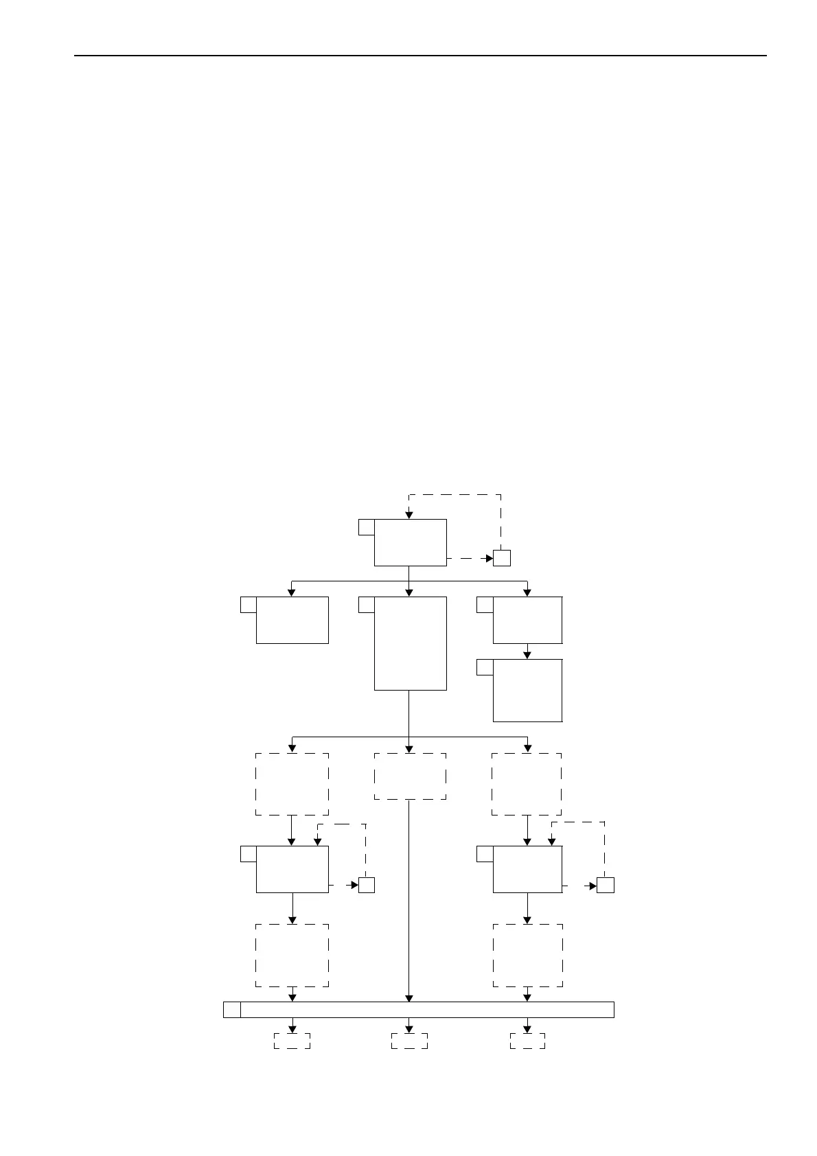
• Flow chart of resetting of electric system
★ The number in the square shows the number of the item for resetting procedure written on pages
20-130 to 20-140.
1
Reset
potentiometer
input signal
Error
2
3
Check
automatic stop
in left offset
4Check
following in
forward and
backward
directions
1) Automatic
stop
2) Stopping
length
9
Correct
indication of
depth
10
Check
automatic
work equip-
ment control
function
Automatic
stop position
is closer than
specified value
Automatic
stop position
is in specified
range
Automatic
stop position
is outside of
the specified
value
5
Reset
automatic stop
output signal
6 Reset
automatic
stop output
signal
Error Error
77
Automatic
stop position
is in specified
range
Automatic
stop position
is in specified
range
8 Move bucket to right and left to check automatic stop position
OK OK OK
 Loading...