20-334 PC58UU-3
TROUBLESHOOTING
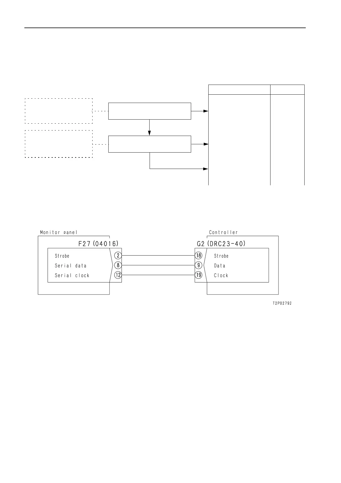
b) When communication system between controller and monitor panel is troubled
a [EE] is displayed on the monitor panel and the work equipment, swing, and travel operations are impos-
sible.
a The LED on the side face of the controller does not light up.
E-17 b) Related electrical circuit diagram (Fault in controller)
Cause Remedy
• Turn starting switch ON
• Disconnect G2.
• Voltage between G2 (9), (18),
(19) – chassis ground:
6 – 10 V
1
Does controller output communication
signals normally?
NO
Defective controller
Replace con-
troller
YES
• Turn starting switch ON.
• Disconnect CN-F27.
• Voltage between F27 (2), (8),
(12) (wiring harness side) –
chassis: 6 – 10 V
2
Defective wiring harness
Defective communication
line: Disconnection or defec-
tive contact in wiring harness
between CN-F27 (2), (8),
(12) - CN-G2 (9), (18), (19)
Does monitor input communication sig-
nal normally?
NO
Repair or
replace wiring
harness
YES
Defective monitor panel
Replace moni-
tor panel
E-17
(6)
 Loading...