DISASSEMBLY AND ASSEMBLY SWING CIRCLE ASSEMBLY
30-38
PC58UU-3
2
12
1. Remove the revolving frame assembly (see
the REVOLVING FRAME ASSEMBLY,
REMOVAL).
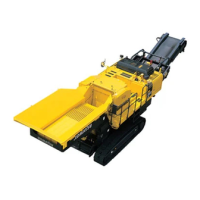
2. Install 4 lifting bolts (having nuts) through the
mounting bolt holes of the revolving frame of
swing circle assembly (1). Temporarily lift the
swing circle assembly using the lifting tool.
Then, remove 20 mounting bolts from the
track frame, and lift and remove the swing cir-
cle assembly.
INSTALLATION OF SWING
CIRCLE ASSEMBLY
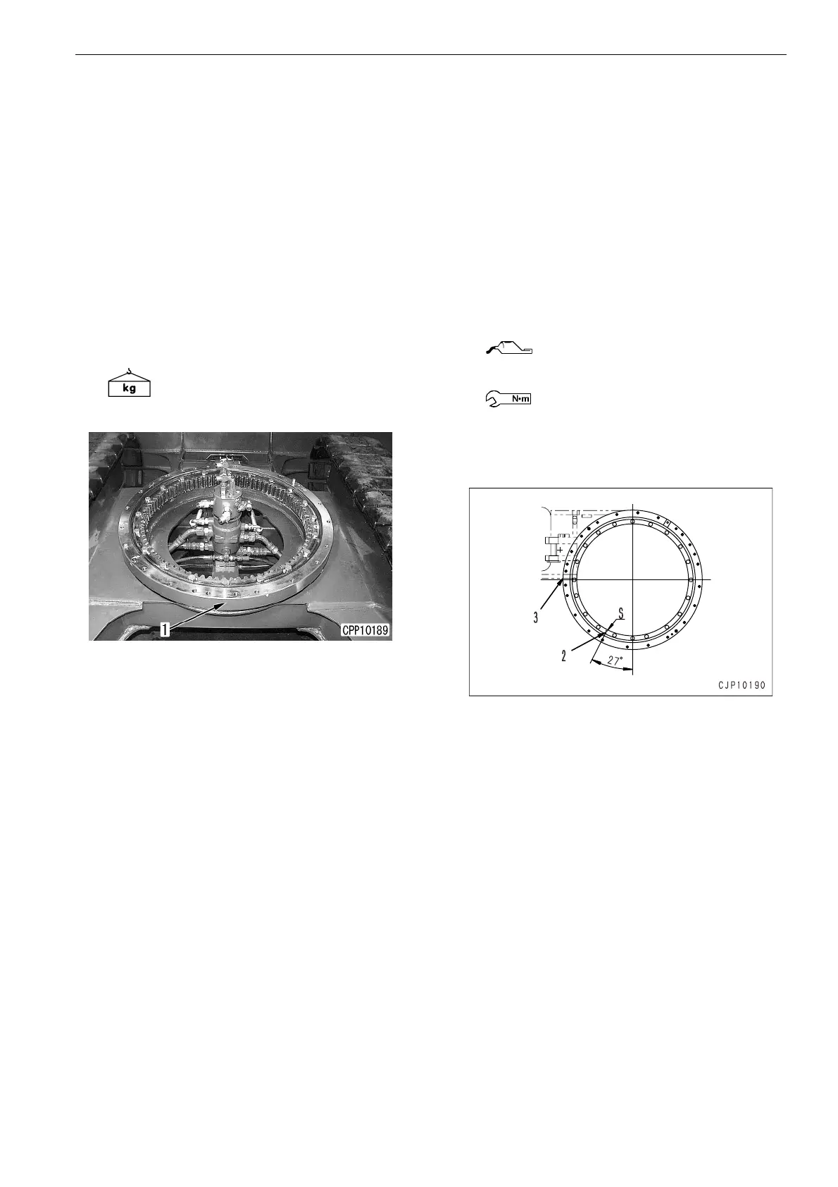
1. Lift the swing circle assembly, align the inner
ring soft zone position (the S marking posi-
tion on the inner ring surface) with S marking
(2) which is 27 degrees shifted toward the left
front position from the turning center line of
right and left inner rings. Place the swing cir-
cle assembly in the specific track frame posi-
tion, and tighten 20 mounting bolts to the
specified torque.
★
Grease the internal gear with plenty of
G2-L1.
★
Point 3 is the machine body front side.
REMOVAL OF
ASSEMBLY
SWING CIRCLE
ASSEMBLY
Swing circle assembly:
Approx. 72 kg
Threads of mounting bolts:
Grease the LT-2.
Mounting bolt:
98 to 122.6 Nm (10 to 12.5 kgm)
 Loading...