.
OPERATION
EXPLANATION OF COMPONENTS
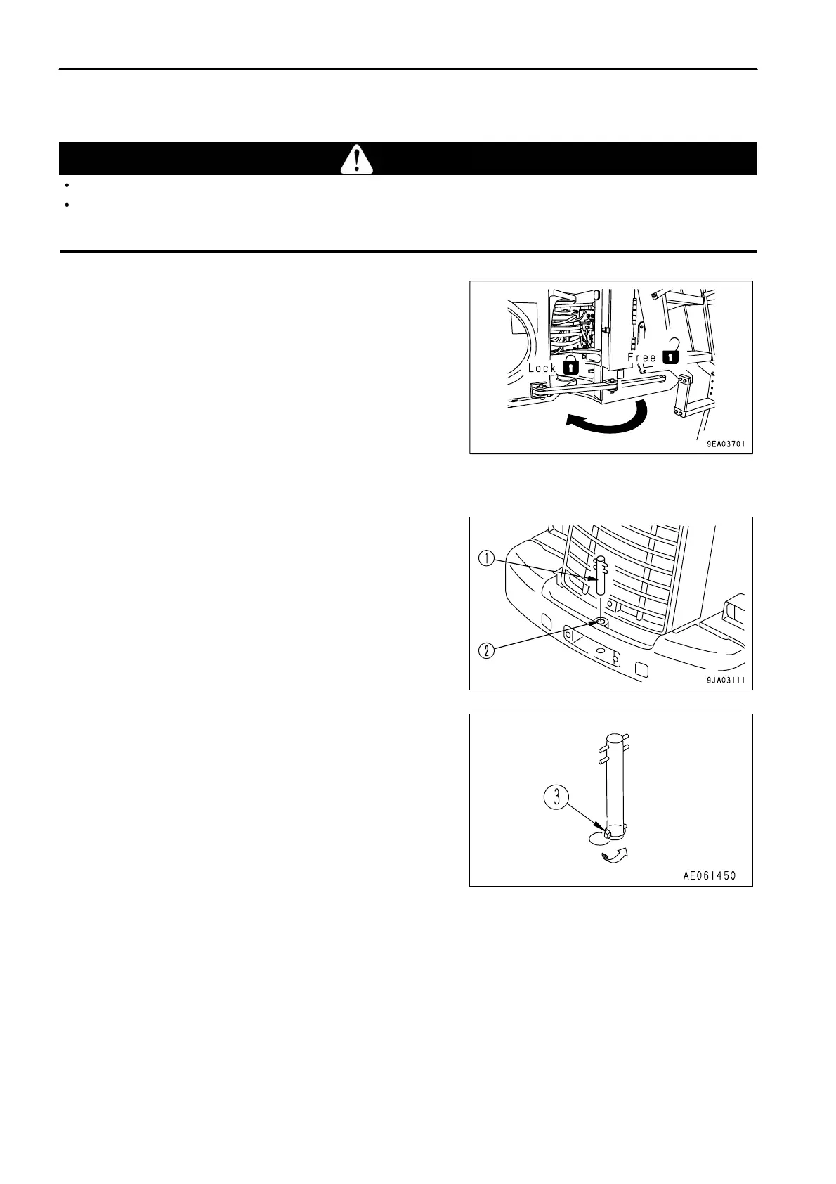
FRAME LOCK BAR
WARNING
When carrying out maintenance or transporting the machine, always set the frame lock bar to the LOCK position.
Always remove the frame lock bar for travel operations. If it is not removed, the steering wheel cannot be used for steering,
and this may lead to serious damage or injury.
This is a device used to lock the front and rear frames during
maintenance or when transporting the machine. It prevents the
front and rear frames from articulating.
TOWING PIN
1.
Insert towing pin (1) into hole (2) in the counterweight.
2. Use linch pin (3) to set so that the towing pin does not come
out.
Reverse this operation to remove the pin.
3 - 58
 Loading...