.
OPERATION
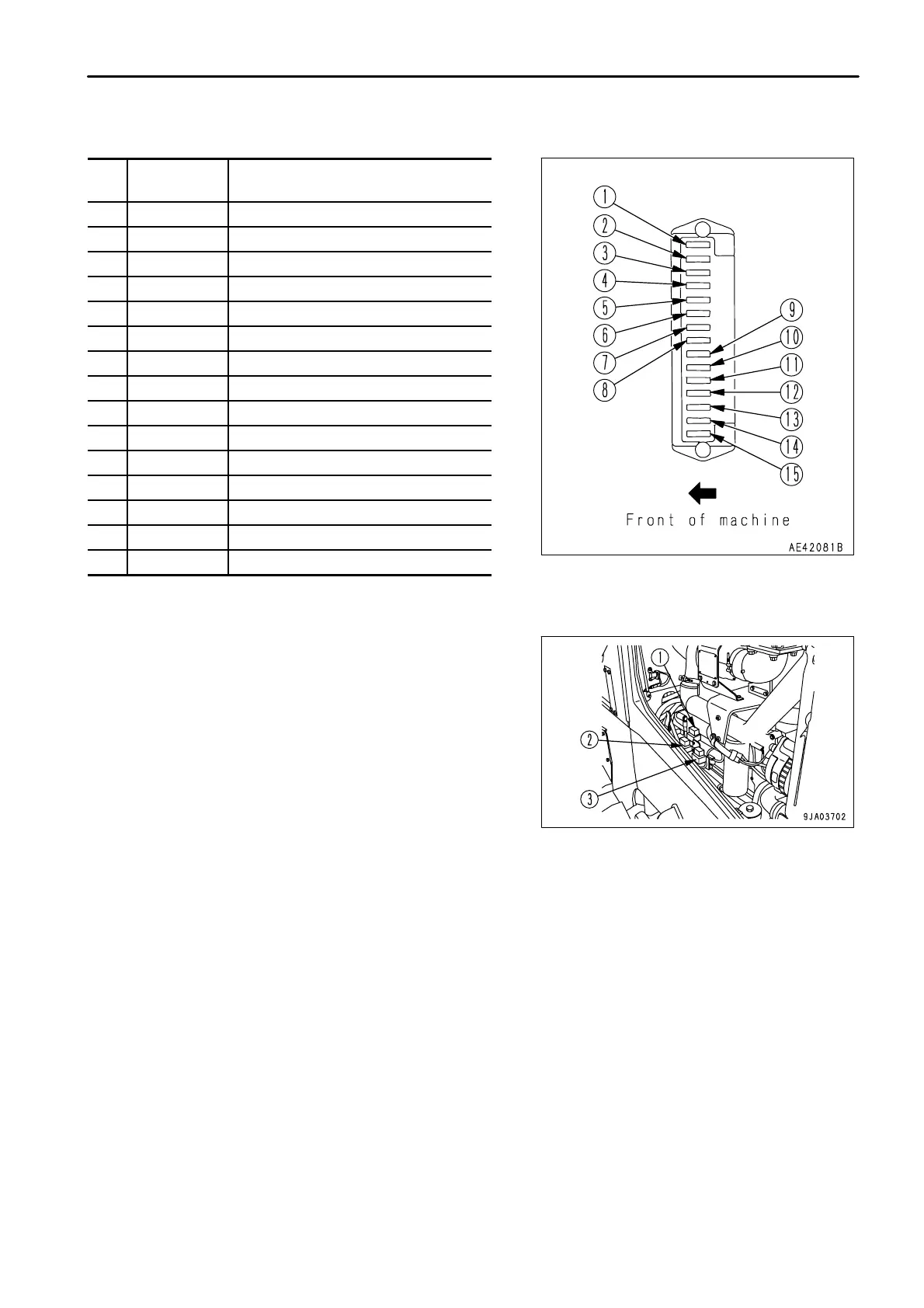
EXPLANATION OF COMPONENTS
FUSE BOX B
No.
Fuse
capacity
Name of circuit
(1) 20A Starting switch
(2) 10A Hazard lamp
(3) 10A Instrument panel A
(4) 10A Room lamp
(5) 10A Spare 1
(6) 20A Power mode selector motor
(7) 10A Turn signal indicator
(8) 20A Front working lamp
(9) 20A Rear working lamp
(10) 10A Instrument panel B
(11) 10A Car radio
(12) 10A Spare 2
(13) 10A DC-DC converter
(14) 20A Air conditioner A
(15) 20A Air conditioner B
SLOW BLOW FUSE
If the power does not come on when the starting switch is turned to
the ON position, there is probably a disconnection in the slow blow
fuse, so inspect and replace it.
The slow blow fuse is on the left side of the machine at the side of
the engine.
SLOW BLOW FUSE
(1)120A: Heater relay (electrical intake air heater)
120A: Main power
(2)40A: Fuel cut-off power source
(3) 30A: Battery power (starting switch, hazard)
30A: After cooler tilt power source (if equipped)
3 - 61
 Loading...