Operation 3.2 Explanation of components
WA470-6H – VEAM946100 3-71
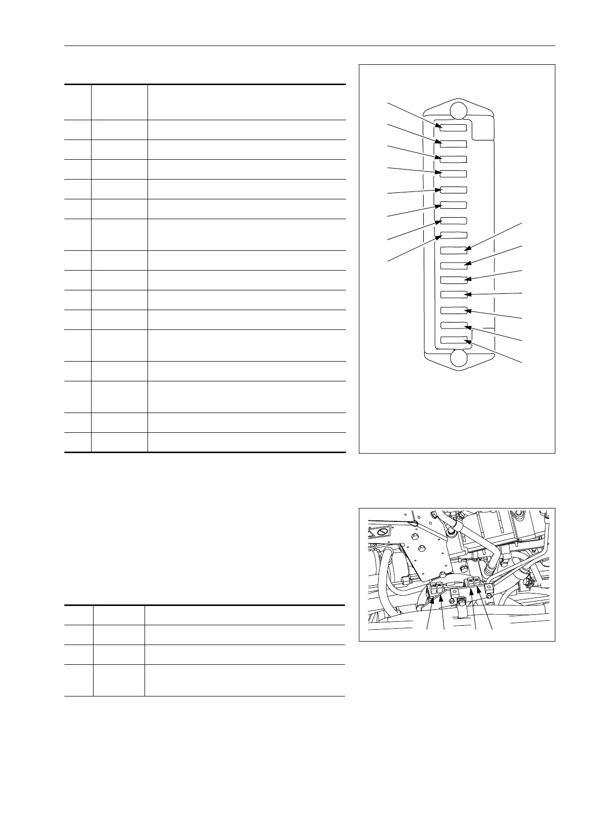
Fuse box B
3.2.14 Slow blow fuse
If the power does not come on when the starting switch is turned
ON, the slow blow fuse may be blown. Check and replace it.
The slow blow fuse is beside the engine on the left side of the
machine.
Slow blow fuse
GK032161
1
2
3
4
5
6
7
8
9
10
11
12
13
14
15
No.
Fuse
capacity
Name of circuit
(1) 5A Engine control B
(2) 20A Rear heated wire glass
(3) 10A Air suspension seat
(4) 20A Yellow rotating lamp (Option)
(5) 10A Turn signal indicator
(6) 20A
Car radio, cigarette lighter,
12V power source
(7) 10A Rear working lamp
(8) 10A Front working lamp
(9) 20A Spare 1
(10) 30A Engine control A
(11) 5A
Transmision control B,
Work equipment controler B (Option)
(12) 10A Room lamp
(13) 10A
Instrument panel A
KOMTRAX (Option)
(14) 10A Hazard lamp
(15) 20A Starting switch
GK047011
1
2
34
(1) 50A Permanent power source
(2) 50A Main power A
(3) 50A Main power B
(4) 120A
Heater relay
(electrical intake air heater)
 Loading...