4.9 Service procedure
Maintenance When required
WA470-6H – VEAM946100 4-33
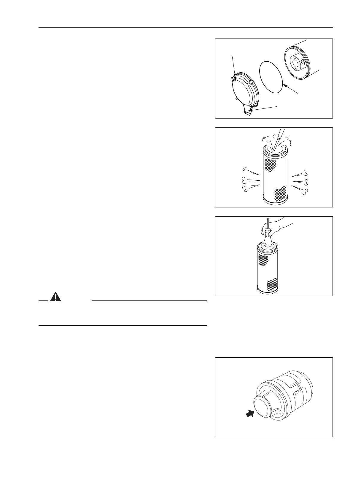
4. Clean the interior of the air cleaner body, cover (3) and evac-
uator valve (6).
NOTE
The inner element must not be used again even after its clean-
ing. When replacing the inner element, replace the outer ele-
ment at the same time.
5. Direct dry compressed air (Max. 0.69 MPa) from the inside
of the outer element along its folds. Then direct the com-
pressed air from the outside along the folds, and again from
the inside.
6. If small holes or thinner parts are found on the element when
it is checked by shining a light through it after cleaning,
replace the element.
NOTE
When cleaning the element, do not hit or beat it against any-
thing.
Do not use an element whose folds, gasket or seal are dam-
aged.
CAUTION
When installing the cover (3), check O-ring (7) and replace it if
there are any scratches or damage.
7. Set the cleaned outer element in position, then secure cover
(3) with mounting clips (2).
8. Press the button of dust indicator to return the yellow piston
to its original position.
9.
Close the engine side cover on the right side of the machine.
After cleaning, if the air cleaner clogging caution lamp lights up
immediately or the yellow piston reaches the red line (7.5 kPa),
replace the inner and outer elements.
GK032240
7
6
3
GK032241
GK032242
GK043050
 Loading...