45
Chapter 2
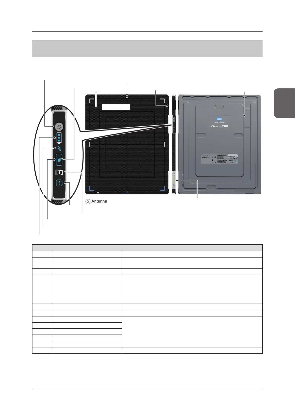
2.2 Component names and functions
2.2.3 AeroDR 3 1417HD/AeroDR 3 1717HD/AeroDR 3 1012HQ
The component names and functions of the DR Detector (AeroDR 3 1417HD, AeroDR 3 1717HD and
AeroDR 3 1012HQ) are as follows.
(12) Wired connection
connector
(5) Antenna
(11) Information LED
(5) Antenna
(6) Back board
(3) Front board
(1) Power SW
(10) Mode LED
(9) Status LED
(8) LINK LED
(7) Battery LED
(2) Selection SW
(4) Triangular mark
Exposure side
Number Name Functions
(1) Power SW Used to turn the DR Detector on/o.
(2) Selection SW
Noties the image processing controller that this DR Detector will be used for
the exposure.
(3) Front board
Protects the internal parts.
(4) Triangular mark
• Indicates the direction to place the DR Detector in during exposure.
– When exposing in portrait, place the triangular mark upward.
– When exposing in landscape, place the triangular mark to the left or right.
(Left and right are set during installation according to the exposure envi-
ronment.)
(5) Antenna Displays the place where a wireless antenna is attached.
(6) Back board
Protects the internal parts.
(7) Battery LED
Toggles DR Detector status displays and the modes.
(8) LINK LED
(9) Status LED
(10) Mode LED
(11) Information LED
(12) Wired connection connector Connects to the AeroDR Battery Charger2, and wired cable.
 Loading...