52
2.2 Component names and functions
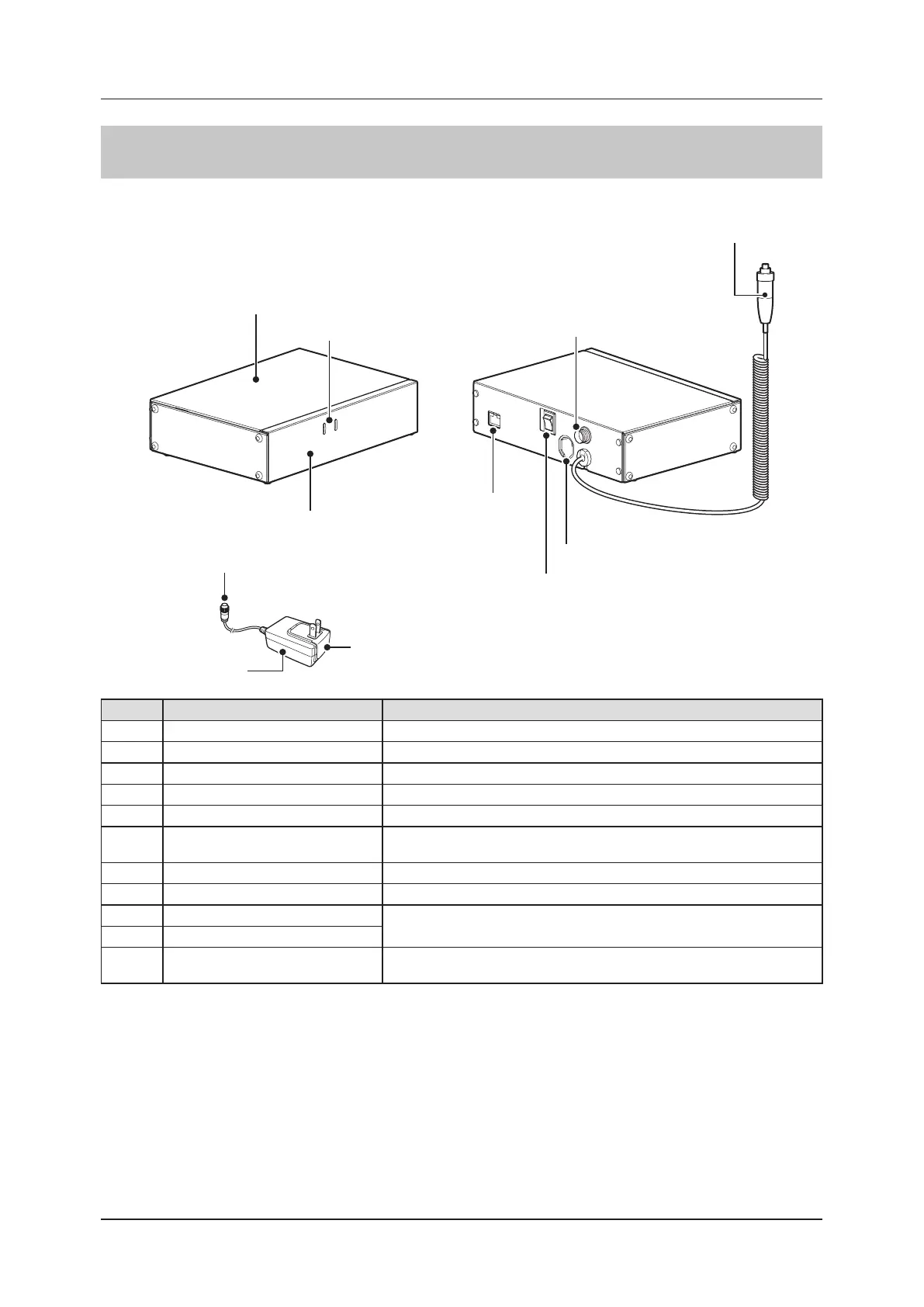
2.2.10 AeroDR Generator Interface Unit2
The component names and functions of the AeroDR Generator Interface Unit2 are as follows.
(2) LEDs
(4) Base BOX
(8) Power cable connector
(10) Power plug
(9) AC adapter
(1) Base cover
(3) Power cable connector socket
(7) X-ray link cable outlet
(5) LAN port
(6) Power switch
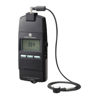
(11) Hand switch
Number Name Functions
(1) Base cover Protects the internal parts.
(2) LEDs Indicate the status of the AeroDR Generator Interface Unit2.
(3) Power cable connector socket This is the socket of the Power cable connector.
(4) Base BOX Protects the internal parts.
(5) LAN port Connects to the Ethernet cable.
(6) Power switch
• Used to turn the AeroDR Generator Interface Unit2 on/o.
• It is only installed when the AC adapter is used.
(7) X-ray link cable outlet Outlet for various X-ray link cables.
(8) Power cable connector Plug into the power cable socket of AeroDR Generator Interface Unit2.
(9) AC adapter
Used to supply power to the AeroDR Generator Interface Unit2.
(10) Power plug
(11) Hand switch
When S-SRM connection is adopted, a hand switch is installed in the AeroDR
Generator Interface Unit2.
 Loading...