47
Chapter 2
2.2 Component names and functions
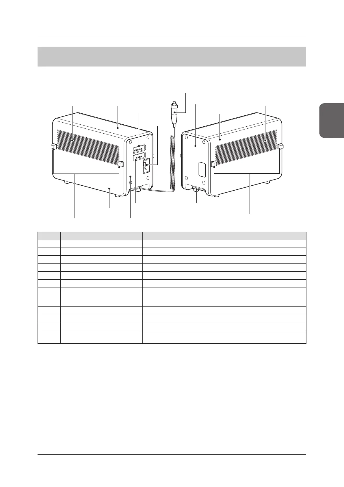
2.2.5 AeroDR Interface Unit2
The component names and functions of the AeroDR Interface Unit2 are as follows.
(1) Exhaust outlet
(7) Spacer
(10) Cable outlet
(6) Side cover
(9) Generator
Interface LEDs
(8) Front cover
(7) Spacer
(1) Exhaust outlet (2) Top cover
(4) Power
switch
(6) Side cover
(5) Rear cover
(11) Hand switch
(3) Detector
Connection
LEDs
Number Name Functions
(1) Exhaust outlet Exhausts internal heat.
(2) Top cover Protects the internal parts.
(3) Detector Connection LEDs Indicate the status of the AeroDR Interface Unit2.
(4) Power switch Turns the AeroDR Interface Unit2 on/o.
(5) Rear cover Protects the internal parts.
(6) Side cover Protects the internal parts.
(7) Spacer
• Prevents exhaust outlet from being blocked after installation.
• No spacers may be provided on some side covers that will not come in contact
with walls.
(8) Front cover Protects the internal parts.
(9) Generator Interface LEDs Indicate the status of the AeroDR Interface Unit2.
(10) Cable outlet Outlet for various cables.
(11) Hand switch
When S-SRM connection is adopted, a hand switch is installed in the AeroDR
Interface Unit2.
 Loading...