55
Chapter 2
2.2 Component names and functions
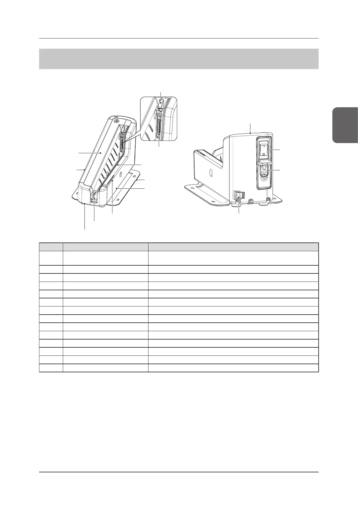
2.2.13 AeroDR Battery Charger2
The component names and functions of the AeroDR Battery Charger2 are as follows.
(4) Stand
(14) LAN connector
(3) Front insert
guide
(2) Wired connec-
tion connector
(1) Connector cover
(5) Front
cover
(9) Rear insert
guide
(10) Rear cover
(11) Side cover (left)
(12) DR Detector insert table
(6) Side cover (right)
(7) Power
switch
(8) Inlet
(13) LEDs
Number Name Functions
(1) Connector cover
Protects the wired connection connector and prevents dust from entering
inside it.
(2) Wired connection connector Connects to the wired connection connector of the DR Detector.
(3) Front insert guide Protects the internal parts.
(4) Stand Protects the AeroDR Battery Charger2 from being overturned.
(5) Front cover Protects the internal parts.
(6) Side cover (right) Protects the internal parts.
(7) Power switch Used to turn the AeroDR Battery Charger2 on/o.
(8) Inlet Connects to the power cable of AeroDR Battery Charger2.
(9) Rear insert guide Protects the internal parts.
(10) Rear cover Protects the internal parts.
(11) Side cover (left) Protects the internal parts.
(12) DR Detector insert table A guide for inserting the DR Detector.
(13) LEDs Indicate the status of the DR Detector and AeroDR Battery Charger2.
(14) LAN connector Connects to the Ethernet cable.
 Loading...