Special equipment
79
Pos: 33.6 /Übersc hriften/Übersc hriften 3/A-E/An bau @ 59\mo d_129766419161 8_78.docx @ 5 58472 @ @ 1
14.4.2 Mounting
Pos: 33.7 /Bei packs/EasyCut/H ydraulische Fe derentlastung/Gef ahr Anbau H ydra. Federentlast ung @ 59\ mod_1297664894 319_78.doc x@ 5 58498 @ 2 @ 1
Danger! - Unexpected movement of the machine
Effect: Danger to life, serious injuries
• There must be nobody between the tractor and machine.
• There must be nobody within the swivel range while the machine is being swivelled from
the transport into the working position or vice versa.
• When leaving the driver's seat, switch off the engine, remove the ignition key, and secure
the tractor against rolling away.
• Wait until all machine parts have come to a complete stop.
• When working under or on the raised machine, support the machine securely.
Pos: 33.8 /WHB/W arnhinweise - Allgemeingültig/Arb eiten an der H ydraulikanlage n ur an druc klosem System @ 9\ mod_121967 0559536_78.doc x @ 120959 @ 3 @ 1
WARNING!
Before working on the hydraulic system, depressurise it.
Pos: 33.9 /Bei packs/EasyCut/H ydraulische Fe derentlastung/GEF AHR! – Einstell ung an den Entlastungsfedern @ 59\mod_12976 65929816_78.doc x @ 558525 @ 2 @ 1
DANGER! – Setting on the compensation springs
Effect: Danger to life or serious injuries
• Set the compensation springs only when the tension has been released (adjusting lever
(a) must be unlocked)
• Compensation springs may be released only in the transport position or headland
position by moving the adjusting lever. In the working position the compensation springs
are subject to high tensile stress when the adjusting lever is locked.
• Severe injury can be caused if the compensation springs are removed while in the
working position.
• The lower threaded blocks on the compensation springs must be fully screwed in.
Pos: 33.10 /Beip acks/EasyCut/Hydr aulische F ederentlastung/O hneC V/De montage der Entlast ungsfedern einzelf eder @ 93\ mod_1327494 583496_78.doc x@ 790193 @ 3 @ 1
Always carry out the removal or the installation of the compensation springs in working
position.
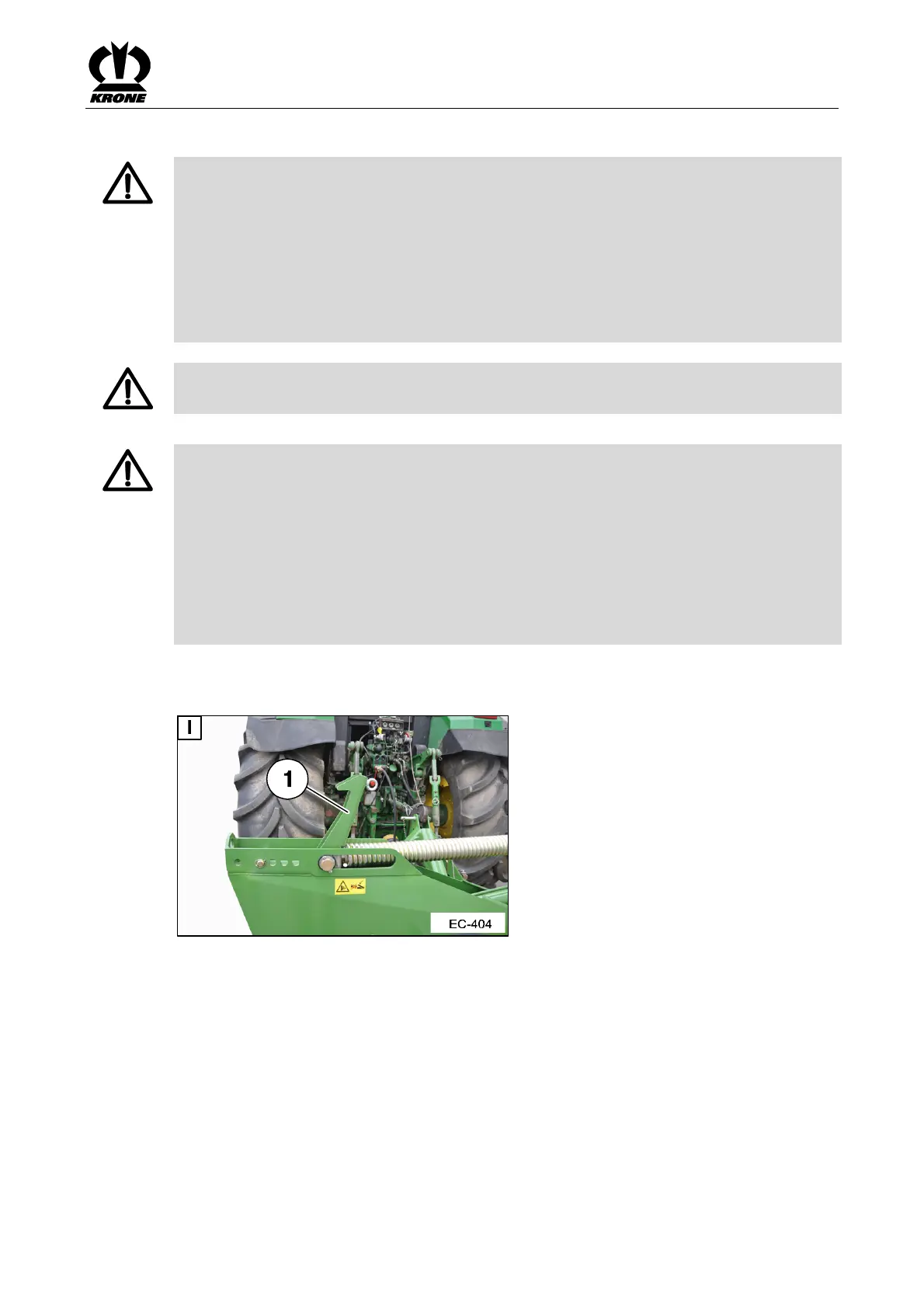
Fig. 48
• Move the machine to the transport position
• Unlock the adjustment lever (1) as shown in the illustration
• Move the machine to the working position
Pos: 33.11 /BA/--- ------ ------Seitenumbruch---- ------------ @ 0\m od_1196175311 226_0.docx @ 4 165 @ @ 1
 Loading...