9MOWER MOUNTING
ENGLISH
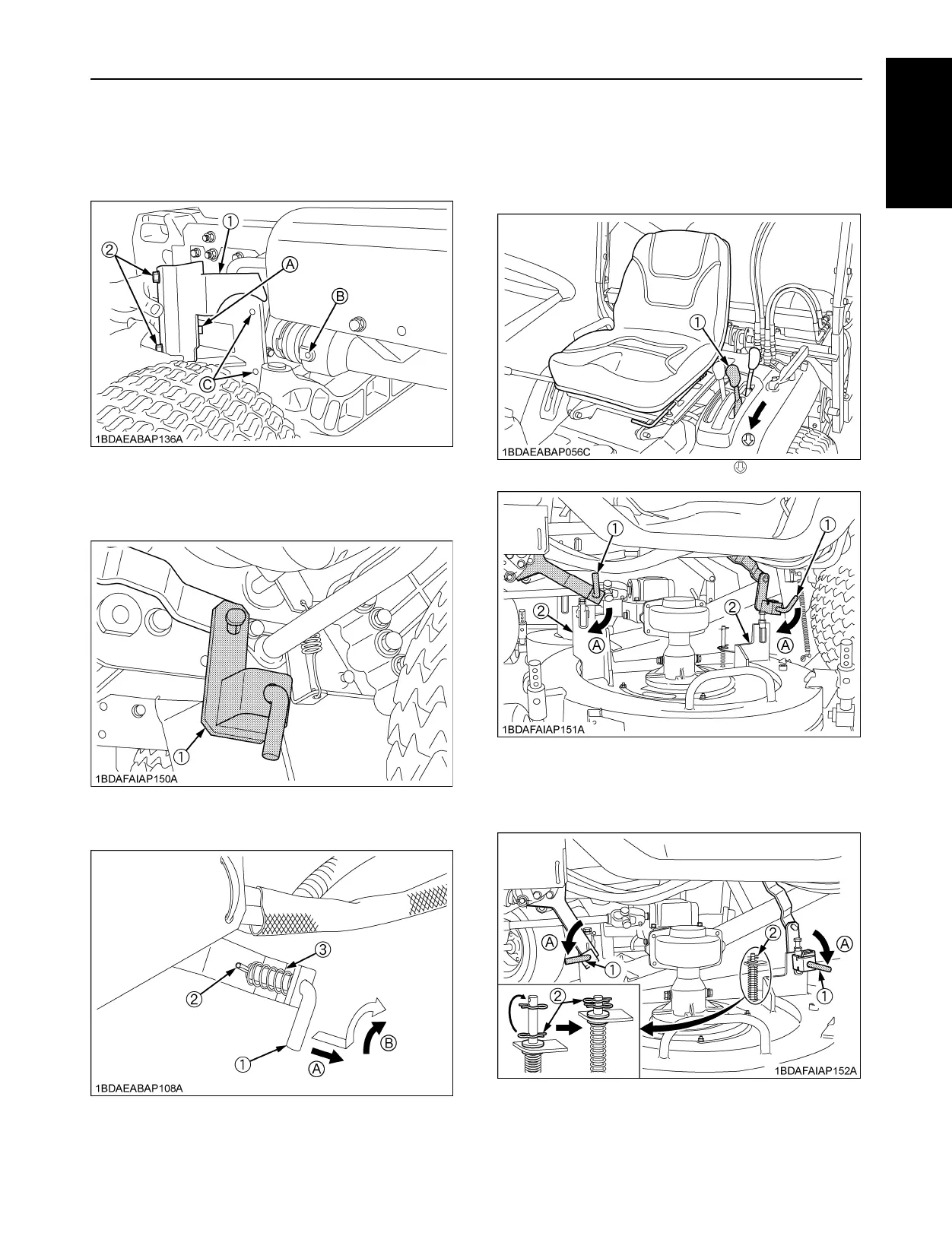
10.[Model with the universal joint cover]
Install the front cover with the two bolts, and then make
sure that the pins are inserted to the hole of the
universal joint cover.
11.Attach the rear arm (LH).
12.Pull and lock the L pins.
13.Turn the cutting height control dial to 0 position.
Place the mower lift lever in the "DOWN" position.
Push down the link arms to align with the mower
bracket.
14.Insert the L pins lock to the mower deck. Move the
lower snap pin to the top position.
15.Start the engine and set the mower at 5 inch position.
(1) Front cover
(2) Bolt
(A) Pin
(B) Hole for the pin (A)
(C) Hole for the bolt (2)
(1) Rear arm (LH)
(1) L pins
(2) Pin
(3) Notch
(A) "PULL"
(B) "LOCK"
(1) Mower lift lever : "DOWN"
(1) L pin
(2) Mower bracket
(A) "DOWN"
(1) L pins
(2) Snap pin
(A) "RELEASE"

 Loading...