19. SWITCHES/HORN/FUEL UNIT/THERMOSTATIC SWITCH
/TEMPERATURE GAUGE/INSTRUMENTS/LIGHTS
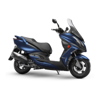
HORN INSPECTION
Remove the front upper cover. (
2-5)
Disconnect the horn wire couplers.
The horn is normal if it sounds when a 12V
battery is connected across the horn wire
terminals.
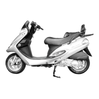
FUEL UNIT
FUEL UNIT INSPECTION
Remove the fuel unit.
Disconnect the fuel unit wire connectors.
Measure the resistance between the fuel unit
wire terminals with the float at upper and
lower positions.
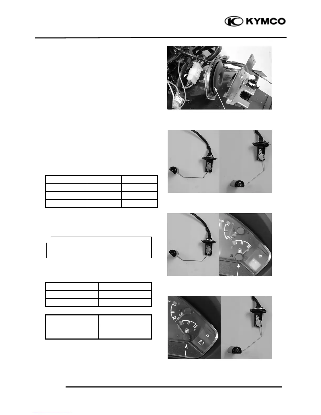
FUEL GAUGE INSPECTION
Connect the fuel unit wire connectors and
turn the ignition switch “ON”.
Check the fuel gauge needle for correct
indication by moving the fuel unit float up
and down.
The fuel gauge is normal if it operates as
above indicated. If not, check for loosely
tightened nuts, poorly connected terminals or
shorted wires.
Before performing the following test,
operate the turn signals to determine that
the battery circuit is normal.
 Loading...