INSPECTION
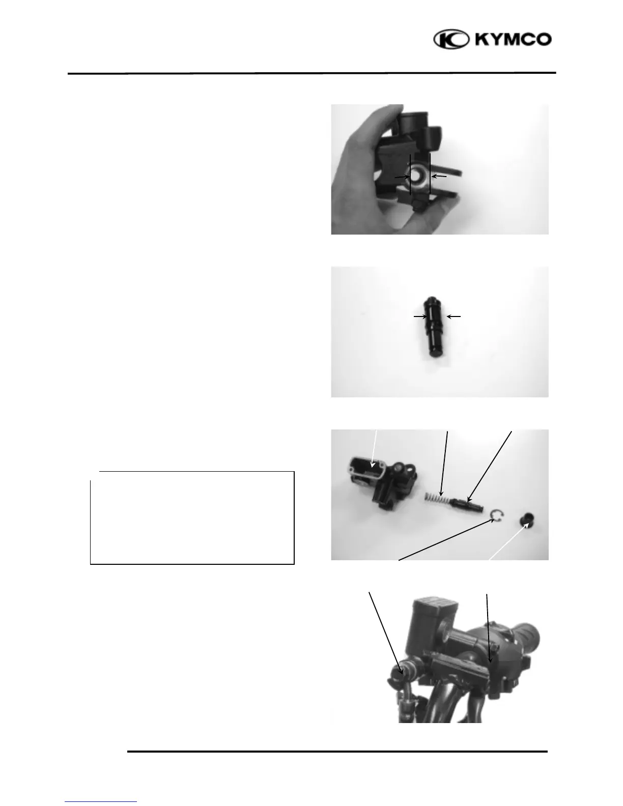
Measure the brake master cylinder I.D.
Inspect the master cylinder for scratches or
cracks.
Service Limit: 12.75mm
Measure the brake master cylinder piston
O.D.
Service Limit: 12.645mm
Before assembly, inspect the lst and 2nd
rubber cups for wear.
ASSEMBLY
Before assembly, apply brake fluid to all
removed parts.
Install the spring together with the 1st rubber
cup.
Install the main piston, spring and snap ring.
Install the rubber cover.
Install the brake lever.
Place the brake master cylinder on the
handlebar and install the holder with the “up”
mark facing up. Also align the punch mark
with the holder joint seam.
First tighten the upper bolt and then tighten
the lower bolt.
Torque: 9.8_ 13.7N-m
Install the brake fluid tube with the attaching
bolt and two sealing washers.
• During assembly, the main piston and
spring must be installed as a unit
without exchange.
• When assembling the piston, soak the
cups in brake fluid for a while.
• Install the cups with the cup lips facing
the correct direction.
 Loading...