12–23
CAL BNC Setup
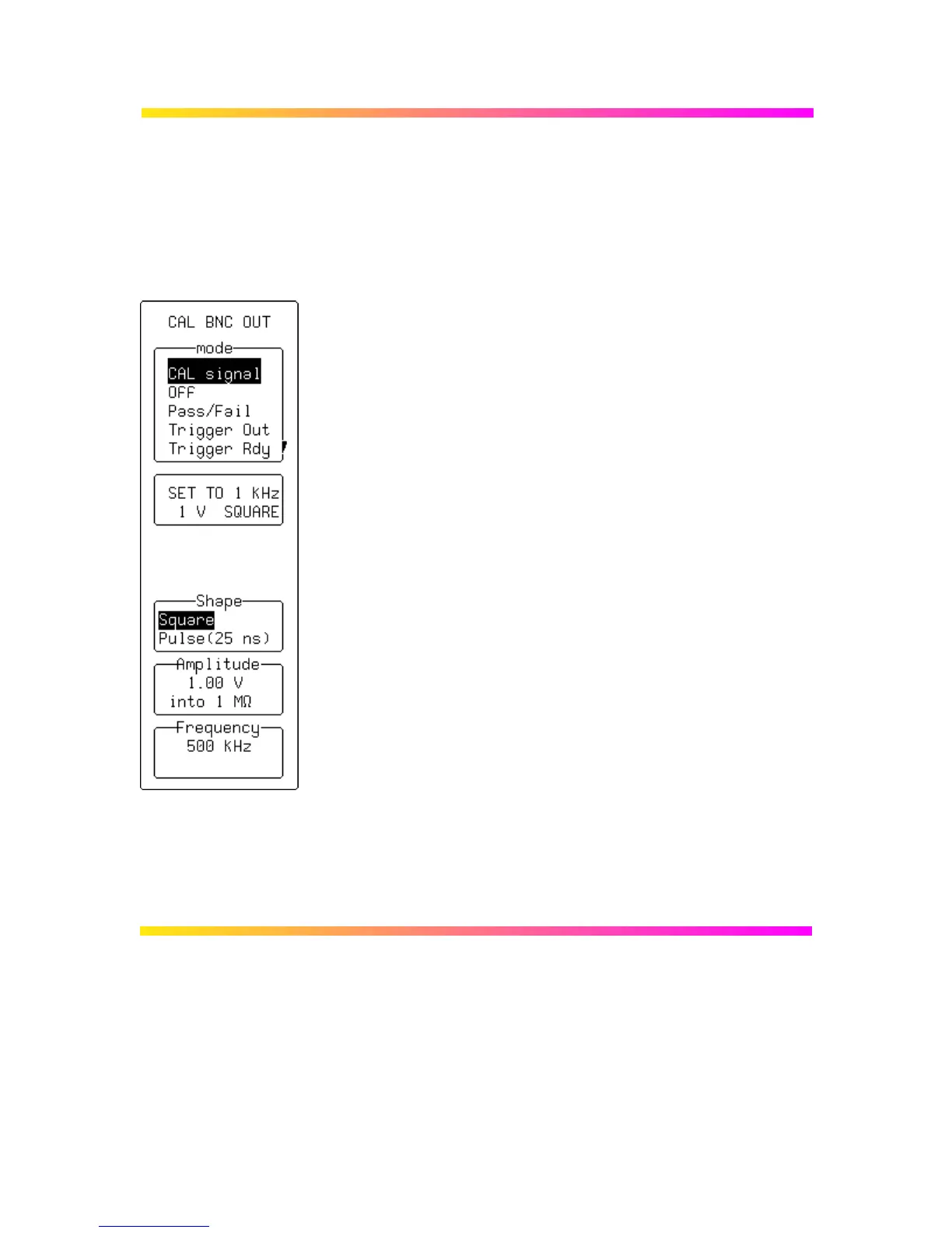
CAL BNC OUT When “CAL BNC Setup” is selected from “UTILITIES”,
selection can be made of the type of signal put out at the CAL
BNC connector. The frequency, amplitude and pulse shape of
the calibration signal can also be chosen.
In addition, the CAL BNC connector can be used to provide a pulse:
Ø as an action for PASS/FAIL testing
Ø at the occurrence of each accepted trigger event (Trigger Out)
Ø when the scope is ready to accept a trigger event (Trigger Rdy).
When the instrument is switched on, the calibration signal is
automatically set to its default state, 1 kHz 1 V square wave.
mode
To change the kind of signal.
SET TO
To quickly reset the CAL BNC output to its default state.
Shape
To change the form of the calibration signal.
Amplitude
Using the associated knob, for setting the desired high level for all
CAL BNC applications. If the BNC output is connected to an input
channel with 50 Ω, the amplitude will be halved.
Frequency
Using the associated knob, for setting the desired frequency of a
CAL signal in the range 500 Hz–2 MHz.

 Loading...