Numbers Components
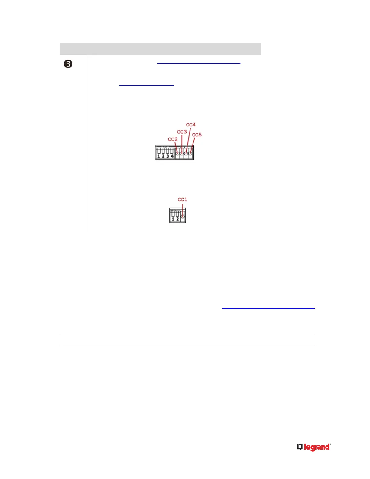
CC status LEDs. For details, see DX2-CC2 Contact Closure Sensor LEDs (on
page 25).
High-speed ashing of CC1 LED indicates that the DX rmware upgrade is in
progress. See Sensor Firmware Update (on page 58).
• Top row:•
The four LEDs, from left to right, indicate the states of CC2,
CC3, CC4 and CC5 respectively.
• Boom row:•
The LED indicates the CC1 state.
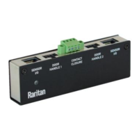
DX-PD2C5 - Powered Dry Contact and Contact Closure
DX‑PD2C5 is physically similar to DX‑D2C6 except for the following dierences:
• Dry contact signal channels of DX‑PD2C5 supply DC 12V power to the connected actuators.•
• Dry contact signal channels of DX‑PD2C5 only support the connecon of EMKA (1150-U5x) door•
handles.
• DX‑PD2C5 works with PX3 PDUs, PX3TS transfer switches and Legrand PDUs only.•
• Maximum cabling length of 29 feet (9 meters). For details, see Supported Maximum Sensor Distance•
(on page 55).
• No asset management strips can be connected simultaneously.•
Warning: If high security is required, it is strongly recommended that DX‑PD2C5 shall NOT be used.
40
 Loading...