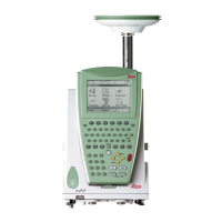
10. Connect the UHF or LTE antenna
to the GS18.
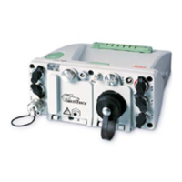
Connect the GEV264 cable to the
GS18, to the external battery
and to the radio housing.
11. Insert the data storage device and the battery into the eld control-
ler.
12. Connect the eld controller to the instrument if necessary.
13. To hang the eld controller on the tripod leg, use the hook on the
hand strap or use the utility hook. Refer to the User Manual of the
eld controller.
14. Insert the height hook into the carrier.
15. Measure the antenna height using the height hook.
16. Press the ON/OFF button on the instrument for at least 2 s to
switch on the instrument.
4.1.3 Setting up as a Real-Time Rover
The equipment setup is used for real-time rover with extended periods of use
in the eld.
Connections are made to the GNSS antenna, radio antenna and eld control-
ler.
The eld controller is xed to the pole with the GHT63. Connection between
the GS18 instrument and the eld controller is made through Bluetooth.
•
The antenna is mounted directly using screw tting. If using stub and
adapter, procedures can vary slightly.
•
When using the pole with stub, ensure that the antenna and the screw-
to-stub adapter slide down the full length of the stub before tightening
the locking ring. An incorrectly mounted antenna will have a direct effect
on the results.
•
Carbon bre poles are used since they are recommended for automatic tilt
compensated measurements. For applications without tilt compensation,
they can be replaced with their aluminium equivalent without any changes
to these instructions.
•
Standard radio is used throughout the instructions. Digital cellular phones
can also be used but the setup can differ slightly.
Use
Description
☞
Operation 29
 Loading...