50
INSTALLATION AND MAINTENANCE
VARMECA 30
Variable speed motor or geared motor
CONNECTIONS
LEROY-SOMER
3776 en - 07.2007 / h
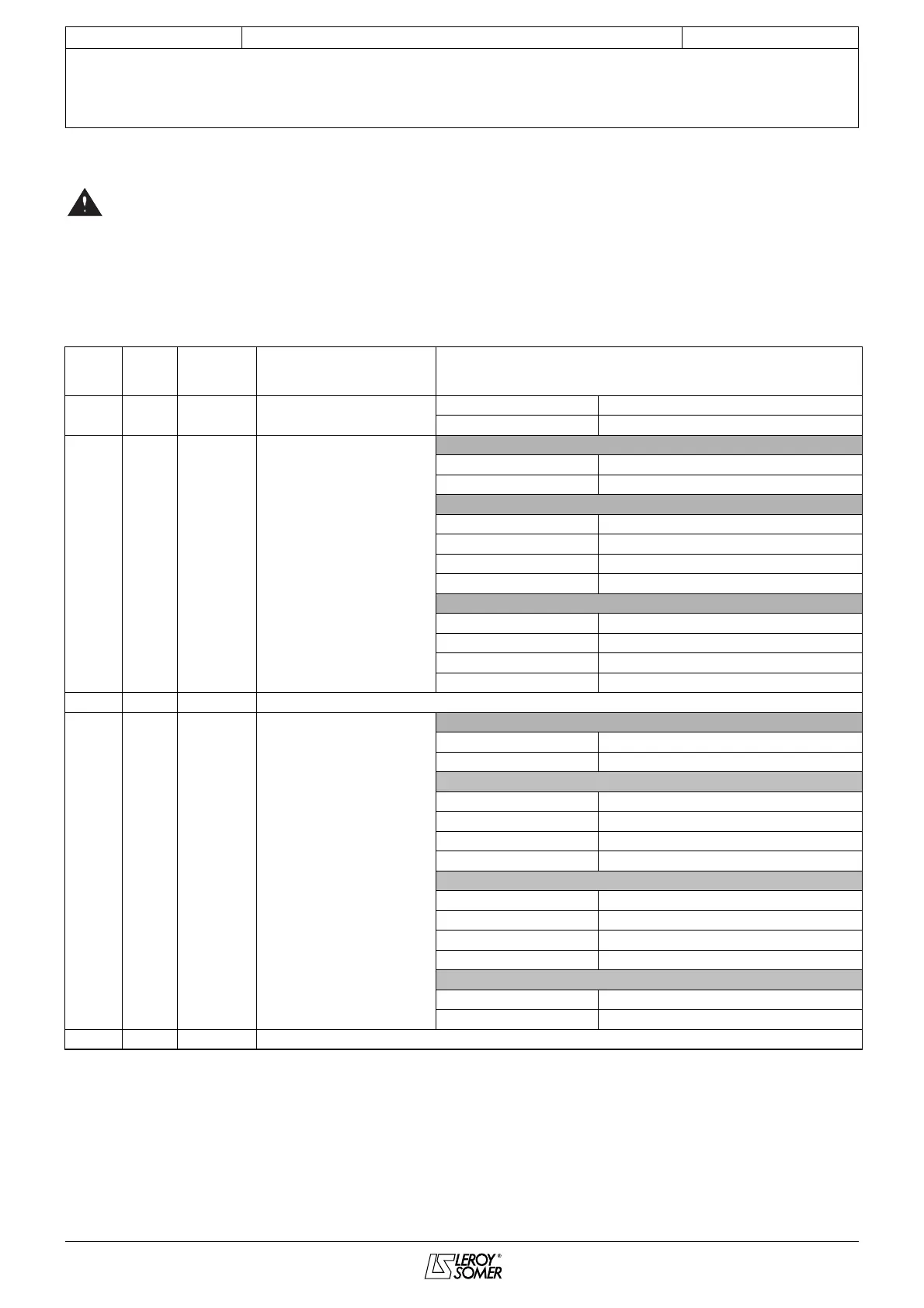
3.2 - Control terminal blocks
• Check that the terminal block has been removed
from its fixed holder (unplugged) before making
any connections, so as to avoid putting pressure on the
card.
• The VARMECA has a positive logic configuration. Using
a drive with a control system which has a different
control logic may cause unwanted starting of the motor.
• The control circuits in the drive are isolated from the
power circuits by single insulation (IEC 664-1).
The installer must ensure that the external control
circuits are isolated against any human contact.
• If the control circuits need to be connected to circuits
conforming to SELV safety requirements, additional
insulation must be inserted to maintain the SELV
classification.
Removable screw terminal block:
- Tightening torque = 0.3 N.m
- Max. cross-section = 1.5 mm
2
VMA
terminal
33/34
VMA
terminal
31/32
Designation Function Characteristics
1 1 10V +10V analogue internal source
Accuracy ± 2%
Maximum output current 30 mA
22 ADI1
Analogue or logic
input 1
Assignment in standard
configuration: 0-10V speed
reference
Voltage input
Full scale voltage 10 V ± 2%
Input impedance 95 k
Ω
Current input
Current range 0 to 20 mA ± 5%
Input impedance 500
Ω
Resolution 10 bits
Sampling 6 ms
Logic input (if connected to the +24V)
Thresholds "0": < 5 V – "1": > 10 V
Voltage range 0 to +24 V
Load 95 k
Ω
Input threshold 7.5 V
3 3 0V Logic circuit common 0V
44
ADI2
Analogue or logic
input 2
Assignment in standard
configuration: Motor PTC input
Voltage input
Full scale voltage 10 V ± 2%
Input impedance 95 k
Ω
Current input
Current range 0 to 20 mA ± 5%
Input impedance 500
Ω
Resolution 10 bits
Sampling 6 ms
Logic input (if connected to the +24V)
Thresholds "0": < 5 V – "1": > 10 V
Voltage range 0 to +24 V
Load 95 k
Ω
Input threshold 7.5 V
Input (PTC)
Trip
≥
3300
Ω
Cleared fault threshold < 1800
Ω
5 NA 0V Logic circuit common 0V
 Loading...