53
INSTALLATION AND MAINTENANCE
VARMECA 30
Variable speed motor or geared motor
CONNECTIONS
LEROY-SOMER
3776 en - 07.2007 / h
en
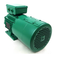
3.5 - Wiring diagrams
3.5.1 - Standard configuration connection diagram
Note:
For single-phase versions, the power supply is connected to terminals L and N.
QS
Indicator relay
Locking input
0-10 V/4-20 mA
speed reference
(local options or external ref.)
Local option indication
External fault input
Forward/Stop
Reverse/Stop
Selection of 0-10 V/4-20 mA
speed reference
Motor PTC input
Braking resistor
(optional)
Jumper to be removed if
optional Braking resistor
connected
Mains supply
10V
ADI1
0V
ADI2
24V
ADIO3
DI01
DI2
DI3
Dl4
+24V
ENA
RL1
RL2
L1
L2
L3
R+
R-
Fi
PE
2
3
4
5
6
1
8
9
10
11
12
7
13
14
VARMECA 31/32
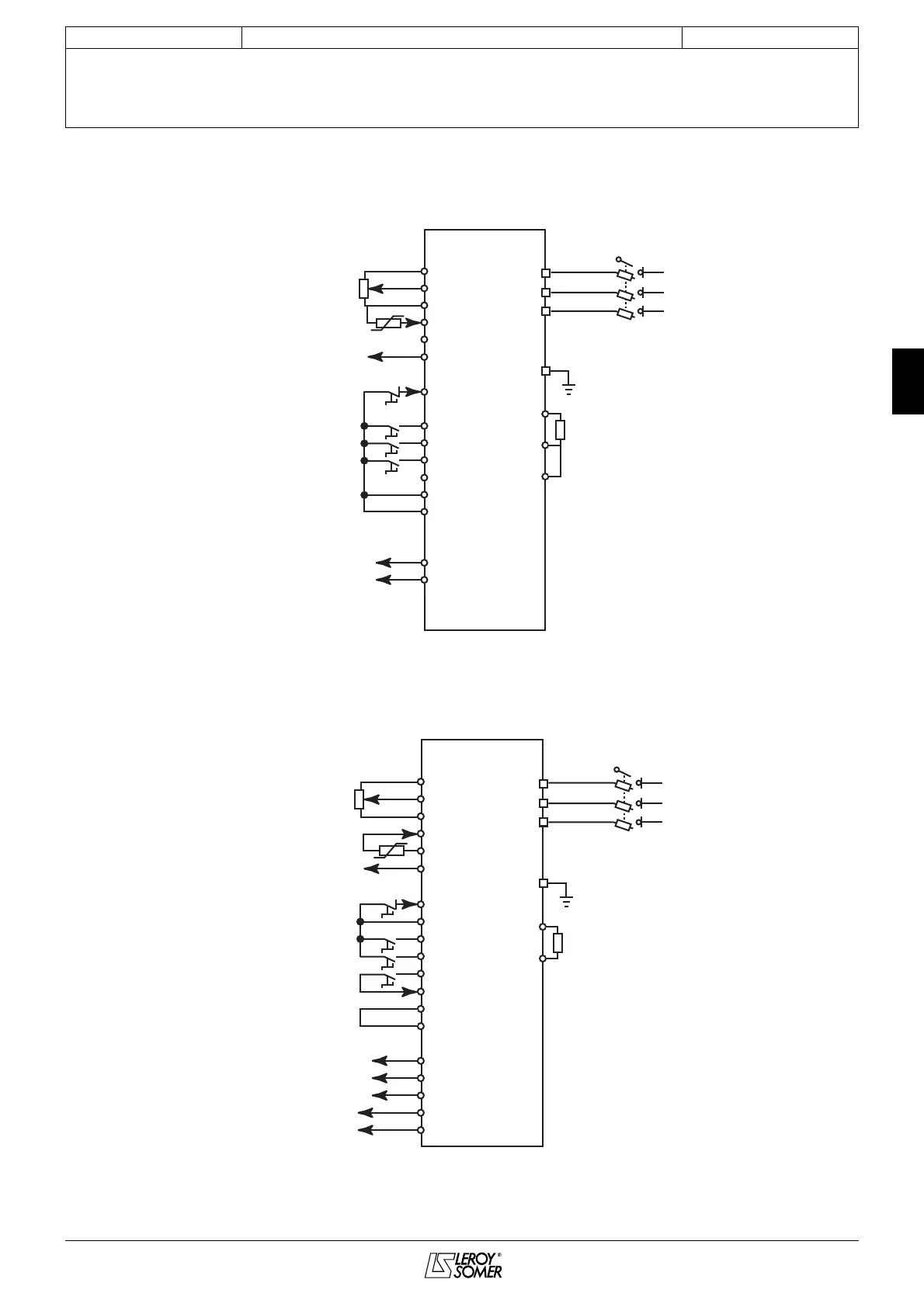
QS
Indicator relay
0-10 V/4-20 mA
speed reference
(local options or external ref.)
Local option indication
External fault input
Forward/Stop
Reverse/Stop
Locking input
Safety contact
Selection of 0-10 V/4-20 mA
speed reference
Motor PTC input
Braking resistor
(optional)
Mains supply
10V
ADI1
0V
ADI2
0V
ADIO3
DI01
+24V
DI2
DI3
+24V
DI4
SDI1
SDI2
COM
RL1C
RL10
SD01
SD02
L1
L2
L3
R+
R-
PE
2
3
4
5
6
1
8
9
10
11
12
13
14
7
15
16
17
18
19
VARMECA 33/34
 Loading...