TRANSMISSION AND TORQUE CONVERTER CD3340B/YB4411
7-14
Published 04/07/2015 Control # 569-00
Troubleshooting (Electrical)
System Operation
Each powershift transmission is provided with electrical
safety locks which inhibit inadvertent operation of the
machine while in an unsafe condition.
When the parking brake is ENGAGED the machine is
prevented from moving by dumping oil in the transmissions’
oil system to the internal oil reservoir. No oil is directed to any
of the drive mechanisms, thereby inhibiting machine
movement. When DISENGAGED the machine will only start
when the shift control lever is in the NEUTRAL position.
Change of machine travel direction is accomplished by
moving the shift control lever, located on the steering
column, from Neutral (center) position up to the FORWARD
position or down to the REVERSE position. Change of speed
range is accomplished by rotating the shift control handle
COUNTERCLOCKWISE to increase the travel speed range
or CLOCKWISE to decrease the travel speed range.
Movement of the shift control lever and rotation of the shift
control handle energizes combinations of solenoid valves
through the ECU, which are connected to two shafts located
in the transmission (See Figure 7-1).
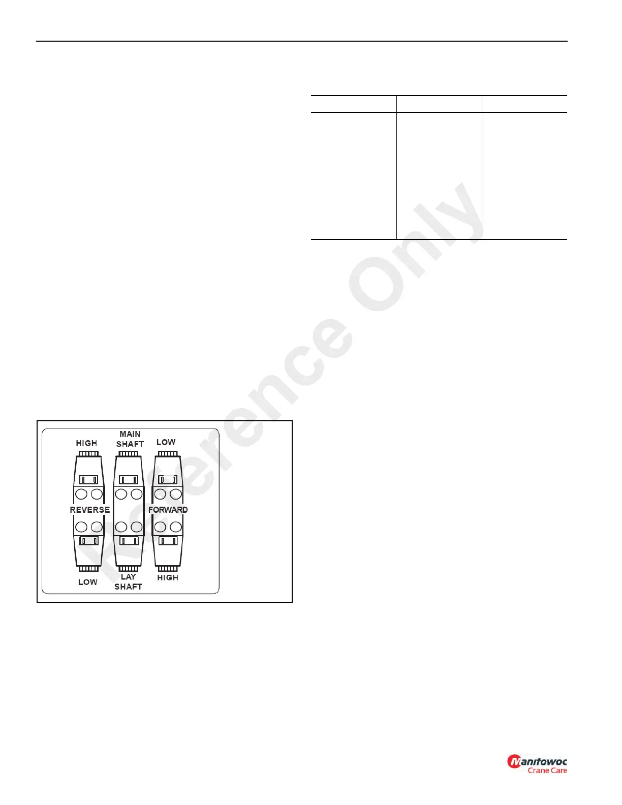
Transmissions are furnished with six solenoid valves (RH,
RL, MS, LS, FL and FH) See arrangement in Figure 7-7. Two
of the solenoid valves control speed ranges while the
remaining four control speed and the direction of travel.
The solenoids are controlled by the transmission Electronic
Control Unit (ECU) and are connected through the wire
harness.
The following table shows which solenoid valves are
energized for the four speeds and two directions of travel.
Table 7-1
Solenoid Valve Energizing Sequence
Electronic Control Unit (ECU)
The Electronic Control Unit (ECU) is designed to do two
things:
a. To control the selection of gears and direction of
travel.
b. To protect the gearbox from damage due to
incorrect use of the controls.
It is a microprocessor controlled unit which is mounted under
the dash in the operators’ cab. A wire harness connects the
ECU to the transmission harness, which connects to the
solenoids, the oil pressure switch and a speed sensor, on the
transmission. A second harness connects the unit to various
switches and selectors in the cab (See Figure 7-8).
The unit receives signals from the gear/direction and other
switches in the cab and operates the appropriate
transmission solenoids accordingly. Built-in software
prevents potentially damaging (and dangerous) selections
from being made. The control features provided by the ECU
software are listed below:
1. Downshift Inhibit - prevents too low of a gear being
selected for a given speed.
2. Kickdown - operated by a button on the shift lever in the
cab - changes down a gear (from 2nd, 3rd or 4th) for a
period of 6 seconds before reverting to the selected
gear.
3. Reverse Inhibit - prevents directional changes if the
speed is too high.
4. Neutral Start - the machine will only start with the shift
control handle in neutral, irrespective of gear selection
(speed) position.
Gear Direction Valves
First
Second
Third
Fourth
First
Second
Third
Fourth
Forward
Forward
Forward
Forward
Reverse
Reverse
Reverse
Reverse
FL and LS
FH and LS
FL and MS
FH and MS
RL and LS
RH and LS
RL and MS
RH and MS
Reference Only

 Loading...


