GROVE 7-17
CD3340B/YB4411 TRANSMISSION AND TORQUE CONVERTER
Published 04/07/2015 Control # 569-00
Finding Electrical Problems
It is possible to carry out a large portion of the ECU
diagnostics with basic workshop tools, such as a test lamp
and/or voltmeter.
NOTE: Never check for voltage directly across any pins on
the ECU. Internal damage can result from shorting
pins.
Checking Solenoid Operation
The correct operation can be confirmed as follows:
1. Chock the wheels.
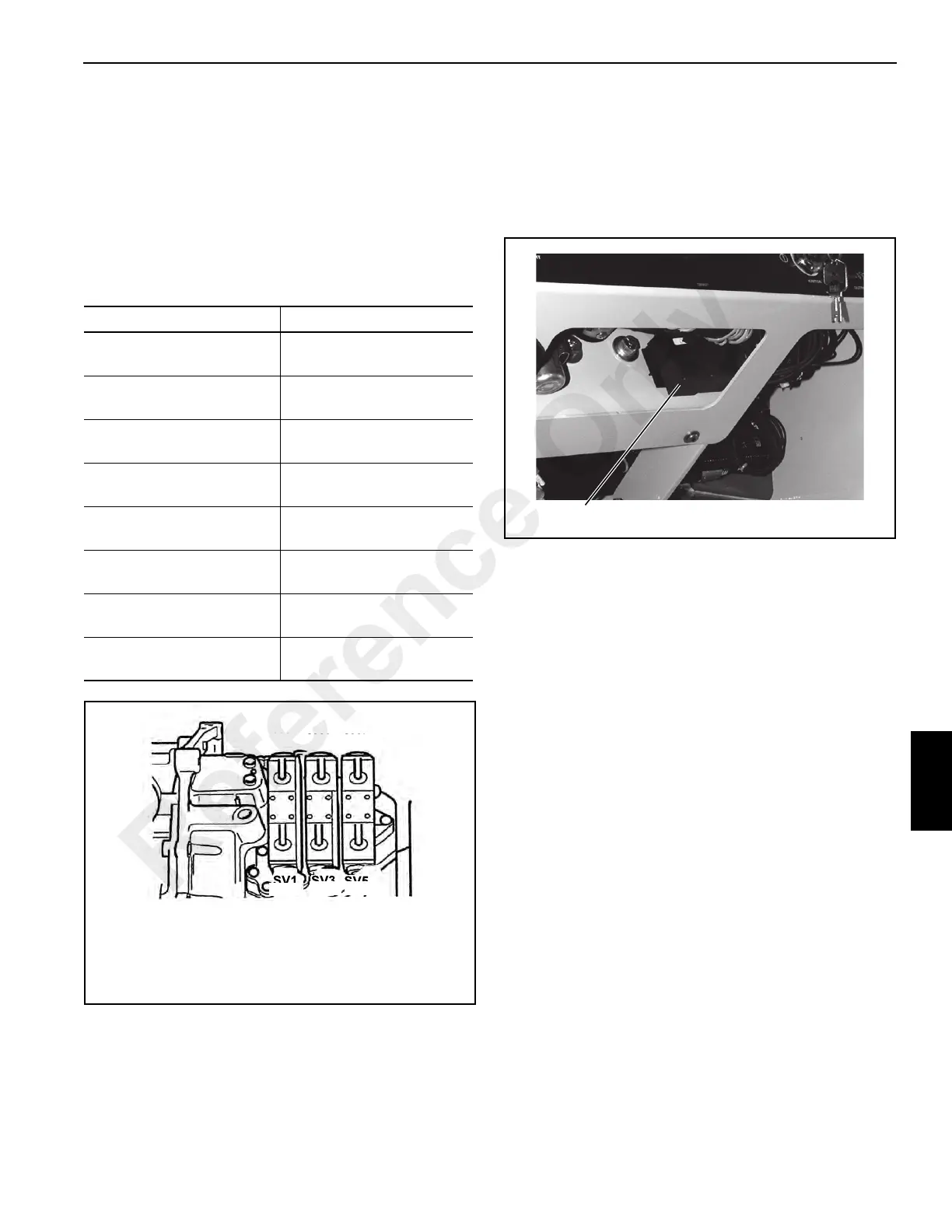
2. Disable the machine neutral start protection to prevent
the engine from starting. This can be accomplished by
removing the neutral start relay located beneath the
dash. See Figure 7-10.
3. Turn the ignition switch to the ON position. Do not set the
parking brake as this dumps the transmission to a
neutral state.
4. Select the desired gear on the shifter control lever.
5. Identify the two solenoids which give the required gear
from Figure 7-9.
6. Check the magnetic attraction on the ends of the
solenoid using a feeler gauge or small screwdriver.
7. If solenoid(s) are not being energized, check that they
are receiving power.
8. If the wrong solenoids are being energized for the gear
selection check the wire harness for proper connections.
9. If the solenoids are being energized correctly and the
problem persists, the problem may be in the
transmission itself or a stuck spool in the solenoid.
NOTE: Here is a simple test if the problem seems to be
intermittent (e.g. transmission dropping to neutral).
Select a gear and place a small washer on the
ends of the energized solenoids. The washers will
be held in place by the magnetic attraction. Drive
the crane around without changing gear or
direction. If the problem reappears examine the
washers. If one or both of the washers have
dropped off, it is a good indication that there is an
electrical problem. In this case, examine the wire
harness and ECU further. If both washers are still in
place the problem lies elsewhere (possibly in the
transmission itself).
Solenoids Figure 7-9
Forward 1st
Forward Low (FL) and
Layshaft (LS)
Forward 2nd
Forward High (FH) and
Layshaft (LS)
Forward 3rd
Forward Low (FL) and
Mainshaft (MS)
Forward 4th
Forward High (FH) and
Mainshaft (MS)
Reverse 1st
Reverse Low (RL) and
Layshaft (LS)
Reverse 2nd.
Reverse High (RH) and
Layshaft (LS)
Reverse 3rd
Reverse Low (RL) and
Mainshaft (MS)
Reverse 4th
Reverse High (RH) and
Mainshaft (MS)
FIGURE 7-9
A0797
RH Reverse High MS Main Shaft
FL Forward Low RL Reverse Low
LS Layshaft FH Forward High
FL
MS
FH
RH
LS
RL
FIGURE 7-10
P0715
Neutral Start Relay Location
Reference Only

 Loading...


