TRANSMISSION AND TORQUE CONVERTER CD3340B/YB4411
7-24
Published 04/07/2015 Control # 569-00
Individual Clutch Leakage Test
In the following procedures the reverse clutch is tested,
therefore, in Step 2 a pressure gauge is connected to the
reverse high clutch test point.
When testing other suspect clutches, connect a gauge to the
relevant suspect clutch pressure test point. See Figure 7-13
for position of individual clutch pressure test points. Because
the reverse high clutch is suspect, a gear must be selected
that will use the reverse high clutch, in this instance 2nd gear
reverse.
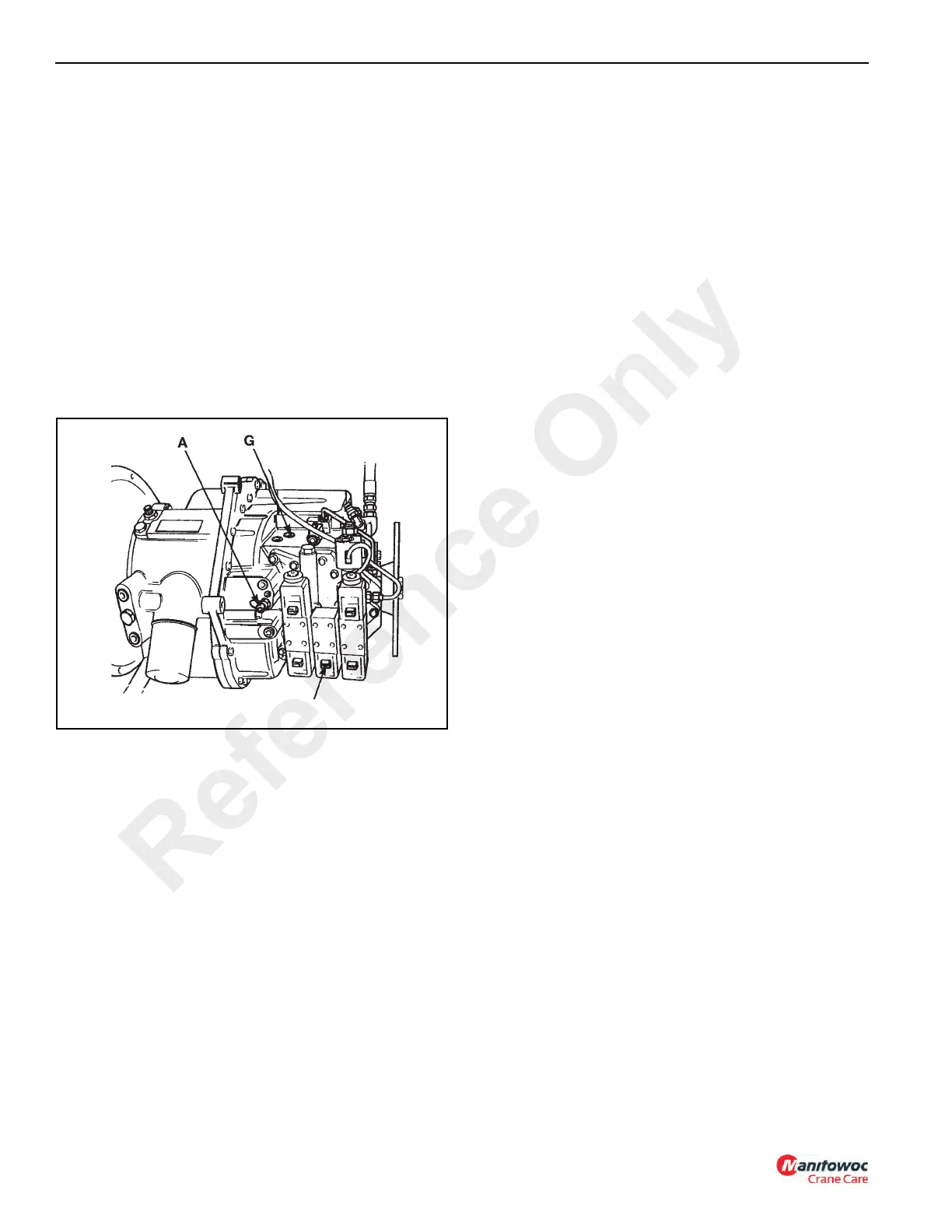
1. Stop the engine and connect a 0-20 bar (0-300 psi)
pressure gauge to test connector A, Figure 7-14
(mainline pressure test point).
2. Connect a 0-20 bar (0-300 psi) pressure gauge to test
point G (reverse high ratio clutch test point).
3. Remove the layshaft clutch solenoid feed connector LS,
Figure 7-14. This ensures only the reverse high clutch is
energized when 2
nd gear reverse is selected.
NOTE: See Figure 7-12 for identification and position of
solenoid feed connectors when testing other
suspect clutches.
4. Raise the tires off of the ground using the outriggers.
NOTE: When performing this test the tires will rotate. Be
careful to stay away from the rotating tires.
5. Start the engine and run at 1000 rpm, select 2
nd gear
reverse. Note the pressure readings on both gauges,
which should not vary more than 0.7 bar (10 psi). If the
difference on the gauges is greater than 69 kPa (10 psi)
do the following:
a. Stop the engine and interchange the gauges.
b. Start the engine and run at 1000 rpm. Select 2
nd
gear reverse. If the difference on the gauges is still
greater than 0.7 bar (10 psi), service the reverse
high clutch.
c. If after interchanging the gauges, the readings are
different than in step 4, have the gauges calibrated
and repeat the test procedure.
Converter Stall Test
NOTE: Engine speed must be recorded during this test.
This machine is not equipped with a tachometer.
One must be installed to perform this test.
NOTE: DO NOT stall the converter longer than10 seconds
or the transmission fluid will overheat. Make sure
that the oil level is correct and at normal operating
temperature.
Before completing the following test, remove the
transmission dipstick. If there is any sign of smoke emitting
from the dipstick tube, STOP THE TEST IMMEDIATELY and
service the transmission.
1. Ensure that the engine and transmission are at normal
working temperatures. Run the engine at maximum
speed and check the High Idle Speed. See Engine
Technical Data in the engine operators’ manual.
2. The crane must not move during this test. Apply the foot
brake firmly. If necessary, set the machine against a
fixed obstruction.
3. Select 2
nd gear forward and run engine at maximum
RPM. Record the engine speed from the tachometer.
Repeat the test for 3
rd gear forward and record the
speed reading.
4. Repeat step 3, except this time select 2
nd gear reverse
and 3
rd gear reverse respectively. Record the speed
readings.
NOTE: Using 2
nd and 3rd gears in forward and reverse will
ensure that all clutches are energized during the
test.
5. All recorded readings should be as specified in Torque
Converter Stall in technical data.
If the engine speeds are below the stated figures, either the
engine is loosing power and should be serviced/overhauled
or the torque converter reaction member clutch is slipping.
To check the engine, select Neutral, open the throttle fully,
and lower the booms fully to bring the main relief over relief.
The engine speed should fall slightly below the Maximum
Governed Speed. If engine speed is correct, the torque
converter reaction member is slipping.
If engine speed is higher than the Maximum Governed
Speed, check the transmission for clutch slippage or internal
leakage. To isolate a suspected clutch, tabulate the recorded
readings as shown in the example below.
Reference Only

 Loading...


