GROVE 7-57
CD3340B/YB4411 TRANSMISSION AND TORQUE CONVERTER
Published 04/07/2015 Control # 569-00
Assembly
Visually inspect the friction and counter plates:
• Counter plates - light scoring/polishing is permissible,
plates that are flat, worn or heavily marked or scored
must be replaced with a new set.
• Friction Plates - the cross hatching should be clearly
visible, plates that are flat, have friction material damage
or scoring must be replaced with a new set.
DO NOT mix old and new plates. If a plate is damaged/worn
install a complete new set.
Needle roller bearings should slide into position freely, do not
bend or distort the cage to install. If the cage has been
distorted, install new bearings.
1. Install new O-ring (26) onto piston (25). Lubricate with oil
and then press piston fully into bore of housing (5).
2. Install inner pressure end plate (24). Make sure the teeth
are not aligned with the lubrication slots in the housing.
NOTE: The inner pressure end plate is 4 mm (0.157 in)
thick and should not be confused with the outer
pressure end plate which is either
6.0 mm (0.23 in) or 6.5 mm (0.25 in) thick.
3. Install one friction plate (22) followed by one counter
plate (23). Continue installing alternating friction and
counter plates. Finish with a friction plate.
4. Install pressure end plate (20). Make sure the teeth are
not aligned with lubricating slots in the housing. Do not
install shim (21) at this stage.
NOTE: A spring disc is not installed in this clutch pack.
5. Install clutch friction/counter plate retaining ring (19).
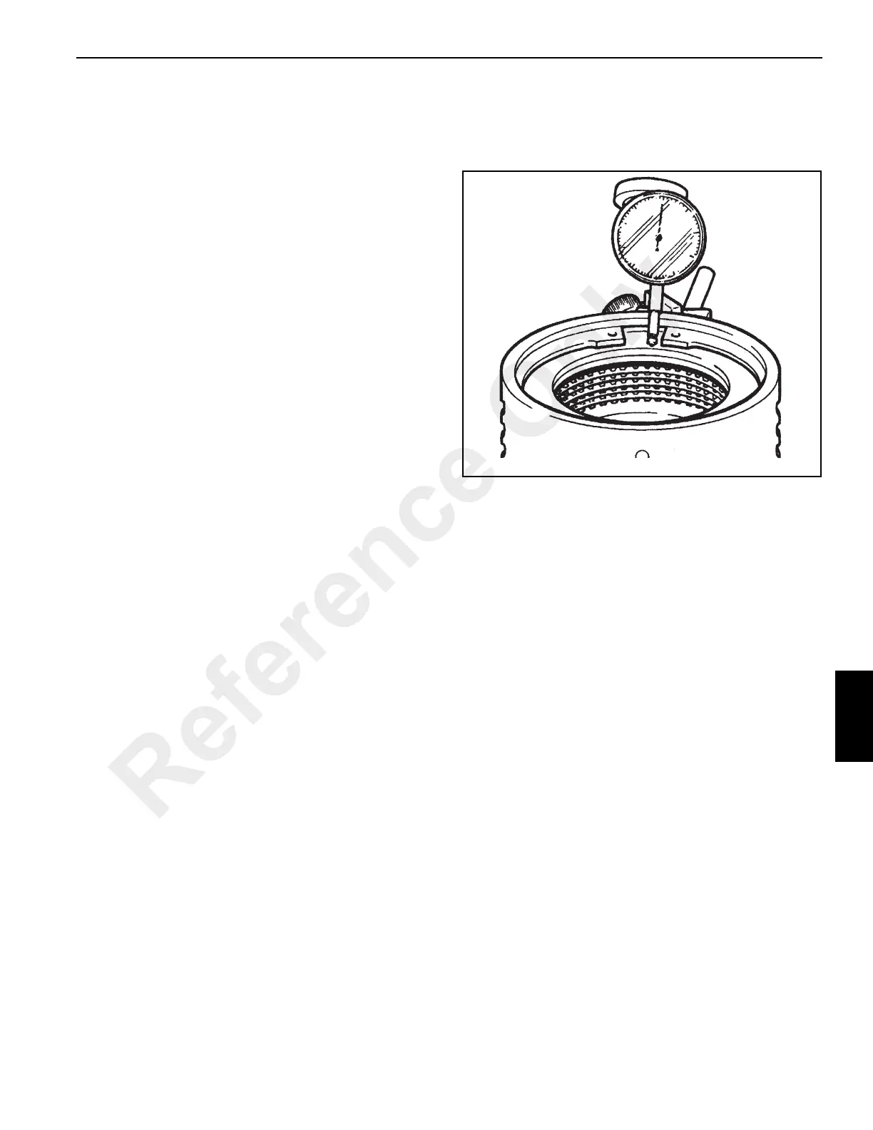
6. Using a dial test indicator as shown in Figure 7-79,
measure the end play of the pressure end plate. End
play should be 1.90 - 2.5 mm (0.075 - 0.098 in).
To adjust the end play, there is a choice between a 6.0 mm
(0.23 in) or a 6.5 mm (0.25 in) pressure end plate (20) with
either a shim (21) or extra counter plate (23) between
retaining ring (19) and pressure end plate (20).
7. Install needle roller thrust bearing (18) and thrust washer
(17).
8. Install two needle roller bearing (16).
9. Install gear and splined hub (12).
10. Install thin thrust washer (15) followed by needle roller
thrust bearing (14) and thrust washer (13).
11. Install retaining ring (11).
12. Install spring retaining plate (8).
13. Install two new O-rings (9 and 10) to the layshaft.
14. Install spring (7) and oil baffle (6).
Reference Only

 Loading...


