AXLES/DRIVE SHAFTS/WHEELS AND TIRES CD3340B/YB4411
8-6
Published 04/07/2015 Control # 569-00
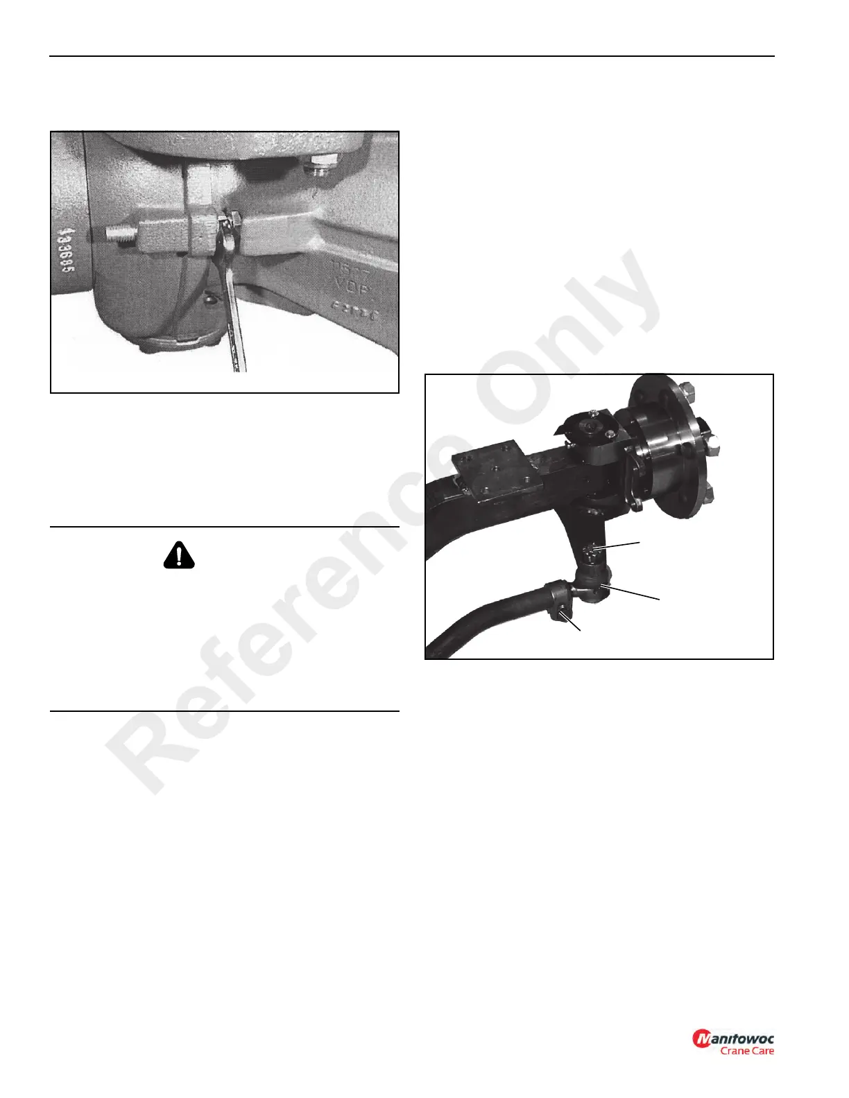
6. Loosen the lock nut on the steering angle screw
(Figure 8-13).
7. Screw the adjusting screw in or out until the correct
angle is obtained.
8. When the angle is adjusted correctly, steer completely in
the opposite direction and repeat steps 3 through 7.
Rear Steering Axle
Checking / Adjusting Toe-in
Checking with Axle on Machine
1. Place the wheels in the straight forward position.
2. Take measurements from the tire to the crane frame at
the four positions A, B, C and D indicated in Figure 8-3.
All four dimensions must be equal.
NOTE: If more than 6 mm (1/4 in) of adjustment is
necessary, make the adjustment on both ends of
the tie rod. Make sure both clamps on the tie rod
are tight when finished.
3. On one end of tie rod loosen the ball joint clamp
(Figure 8-14).
4. Remove the cotter pin from the castle nut. Remove the
castle nut.
5. Remove the ball joint from the steering knuckle.
6. Either screw the ball joint in or out to obtain equal
dimensions.
7. When the correct dimensions are obtained, tighten the
castle nut and install the cotter pin.
8. Tighten the ball joint clamp.
WARNING
A raised and badly supported machine can fall on you
causing severe injury or death. Position the machine on a
firm, level surface before raising one end. Ensure that the
other end is securely chocked. Do not rely solely on the
machine’s hydraulics or jacks to support the machine
when working under it.
Disconnect the battery cables while you’re under the
machine to prevent the engine from being started.
FIGURE 8-14
P0690
Cotter Pin and Nut
Ball Joint
Ball Joint Clamp
Reference Only

 Loading...


