STRUCTURAL CD3340B/YB4411
11-22
Published 04/07/2015 Control # 569-00
the extra two tapped holes (Figure 11-34) and tighten
them evenly until the brake housing has come loose
from the mounting bracket. See Brake Section for repair
instructions.
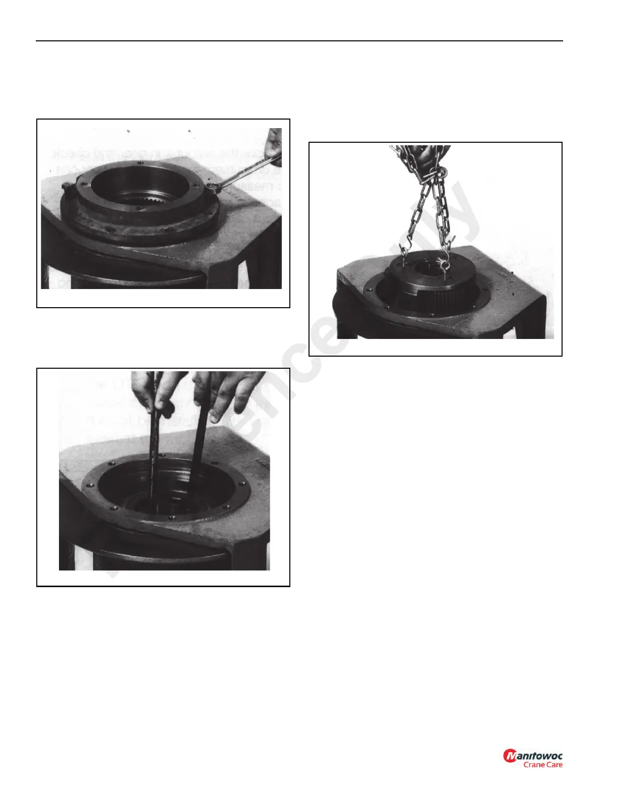
4. Using two crows foot pry bars (Figure 11-35), hook the
bearing carrier (11, Figure 11-33) from inside and pull it
out of the cable drum. Remove the bearing (5) and seal
(4) from the bearing carrier (11).
5. Remove the input sun gear (9, Figure 11-33) from the
input planet set (22).
6. Install three 1/4 inch eyebolts (Figure 11-36) into the
three planet pins in the input planet set (22,
Figure 11-33). Use a piece of chain (Figure 11-36) to pull
the planet set from the drum. Inspect the planet set for
wear and repair as needed. See Planet Sets for repair
instructions.
7. Remove the output sun gear (16) and check drum (10)
teeth for wear. This wear can be measured as follows:
a. Place a magnetic base dial indicator on the output
carrier (8, Figure 11-33) and adjust the plunger of
the dial indicator approximately at the middle of one
of planet gear teeth.
b. Using a screwdriver or your finger, rotate the planet
gear back and forth, reading the movement on the
dial indicator. If the total movement is greater than
0.64 mm (0.025 in), then the drum should be
replaced.
Using the same procedure as in Step 6, remove the
output planet set (23, Figure 11-33) from the drum.
Inspect the planet set for wear and repair as necessary.
See Planet Sets for repair instructions.
8. Turn the hoist over onto the motor end and remove the
capscrews holding the output shaft (3, Figure 11-33) into
the mounting bracket. Reference mark for proper
assembly. Install two of the capscrews into the extra
threaded holes in the output shaft (Figure 11-37) and
evenly tighten them until the output shaft is free from the
mounting bracket.
Reference Only

 Loading...


