GROVE 4-33
CD3340B/YB4411 HYDRAULIC SYSTEM
Published 04/07/2015 Control # 569-00
4. Slowly loosen spool end shoulder screw (30). The screw
is under pressure from spring (21), be sure to hold the
spring seats (31) and spring (21) when removing screw
(30).
5. Remove spring seats (31) and spring (21). On end cap
assembly (29A), remove spring (20).
NOTE: Valve section 2 has a different spring than valve
sections 5, 6 and 7. Be sure not to mix the springs.
6. If equipped, remove anti-void valve assembly (14).
7. If equipped, remove port relief (6).
8. Remove shut-off plug(s) (3).
9. If a valve spool must be removed, keep it with its valve
housing. Do not mix valve spools and valve housings.
Assembly
Spool Section
1. If any valve spool was removed from its valve housing,
apply petroleum jelly to the spool and then insert the
spool into the section.
2. Coat all seals with a light coat of hydraulic oil, and then
install O-ring (17, Figure 4-17), O-ring (18) and backup
ring (19) onto retainer (32).
3. Install two spring seats (31) and spring (21) in end cap
(29 or 29A). On end cap (29A), also install spring (20).
Secure these items using spool end shoulder screw
(30). Tighten the screw to a torque of 8.2-10.8 Nm (6-8
lb-ft).
4. Install the end cap assembly and secure with two socket
head capscrews. Tighten to a torque of 8.2-10.8 Nm (6-8
lb-ft).
5. Install O-ring (17) onto cap assembly (22). Attach the
assembly to the valve housing using two socket head
capscrews. Tighten to a torque of 8.2-10.8 Nm (6-8 lb-ft).
6. Install the shut-off plug(s) (3). Tighten to a torque of
39.4-50.0 Nm (29-36 lb-ft).
7. If equipped, install the anti-void valve assembly (14).
Tighten to a torque of 39.4-50.0 Nm (29 - 36 lb-ft).
8. If equipped, install port relief valve (6). Tighten to a
torque of 39.4 - 50.0 Nm (29 - 36 lb-ft).
Complete Valve Assembly
1. Lay the valve components on a clean, flat work surface.
2. Assemble nuts (10 and 12, Figure 4-17) to one end of
each stud (9 and 11). Insert the studs through the stud
holes in the inlet valve section (1). Lay the inlet section
on the work bench with the studs facing up.
3. Place O-ring (24) in position on the face of the inlet
section.
4. Place the first spool valve section (2) (Swing), O-ring
side up over the studs onto inlet section (1). Place O-ring
(24) in position on the face of the valve section. Install
the load check poppet (28) and spring (27) into the load
check cavity. Be sure the nose of the check poppet is
facing down.
5. Install mid-inlet section (16) over the studs and onto
valve section (2). Position O-ring (24) on the mid-inlet
section.
6. Install the second spool valve section (5) (Telescope).
Position O-ring (24) on the valve section.
7. Repeat step 6 for the third and fourth spool valve
sections (6 - Hoist) and (7 - Lift).
8. Position load sense valve section (8) on the last working
valve section and hand tighten stud nuts (10 and 12).
9. Position the valve assembly with the mounting pads of
the end sections on a flat surface. To obtain proper
alignment of the end sections relative to the spool
sections, apply a downward force. Snug tie rod nuts (10
and 12) to about 13.6 Nm (10 lb-ft). Final torque is 44.8
Nm (33 lb-ft) on larger nut and 19 Nm (14 lb-ft) on the
smaller nuts.
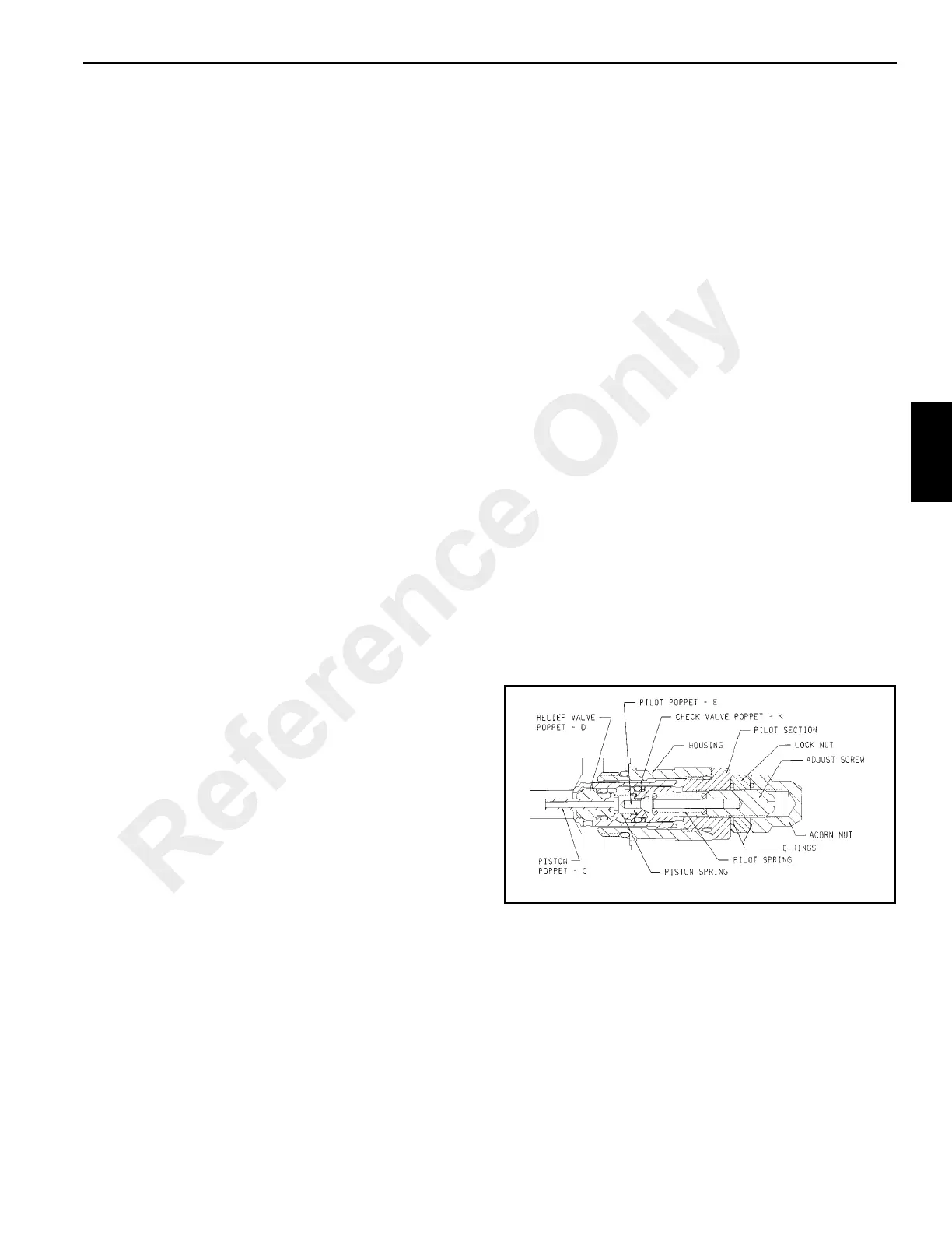
Main Relief and Port Relief Valves
The cartridge-type relief valves are typically of the pilot
poppet type with external adjustment. Any malfunction is
usually the result of foreign matter lodging between the
piston (see Figure 4-18), the relief valve poppet and the
check valve.
To perform service, clean the surrounding area and remove
the complete relief valve cartridge. Examine the seat in the
main relief housing and if grooves and ridges are evident, the
valve must be replaced.
The design of the pilot poppet and its seal provides positive
seating and very seldom requires any maintenance.
Therefore, the pilot section can be removed from the
cartridge housing without disturbing the pressure setting.
With it will come the check valve poppet and other internal
parts. These are easily disassembled and should be
examined for foreign material. All seats and seating surfaces
Reference Only

 Loading...


