Matrix ETERNITY Quick Start 41
• By default J5 is set to BC position to provide 120 termination resistance for E1
connectivity.
• To set 100 termination resistance for T1 connectivity, set jumper J5 to AB
position.
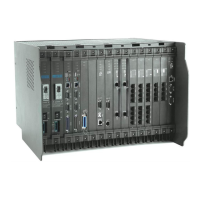
In ETERNITY PE
Termination Resistance of the PRI Port for T1 or E1 Connectivity is set by changing
the position of the Jumper J2 as given in the table below:
By default the jumper J2 is in BC position to provide 120 for E1 connectivity.
To se t 1 0 0 termination resistance for T1 connectivity, set jumper J2 to AB position.
• Connect one end of the RJ45 cable provided with the T1E1PRI Card of
ETERNITY ME/GE/PE to the T1E1 Port and the other end to the modem
provided by the ISDN Service Provider.
LED indication of T1E1PRI Card of ETERNITY-ME and ETERNITY-GE are
shown below. There are no LEDs on T1E1PRI Card of ETERNITY PE.
LED indication on ETERNITY-ME T1E1PRI Card
• The ETERNITY ME T1E1PRI Card has four LEDs: L1, L2, L3 and L4.
• LED L1 and L2 are assigned to T1E1 Port 1, while LED L3 and L4 are assigned
to Port 2.
• LED L1 shows Card Heart Bit as well as status of the Port1.
LED indication on ETERNITY-GE T1E1PRI Card
• The ETERNITY-GE T1E1PRI Card has 2 LEDs: LED1 and LED2.
• LED patterns are defined as shown below for different state and signaling as
shown below.
Jumper Position Meaning
J2 BC To set termination resistance of 120 for E1 connectivity
J2 AB To set termination resistance of 100 for T1 connectivity
 Loading...