© 2009 MIMAKI ENGINEERING CO.,LTD.
2.3.6 P.1
1
2
3
4
5
6
7
8
R.1.1
Maintenance Manual > Electrical Parts > Circuit Board Specifications > Station PCB Assy
Model CJV30/TPC Issued 2008.08.04 Revised 2008.09.17 F/W ver. 1.20 Remark
1.1
2.3.6 Station PCB Assy
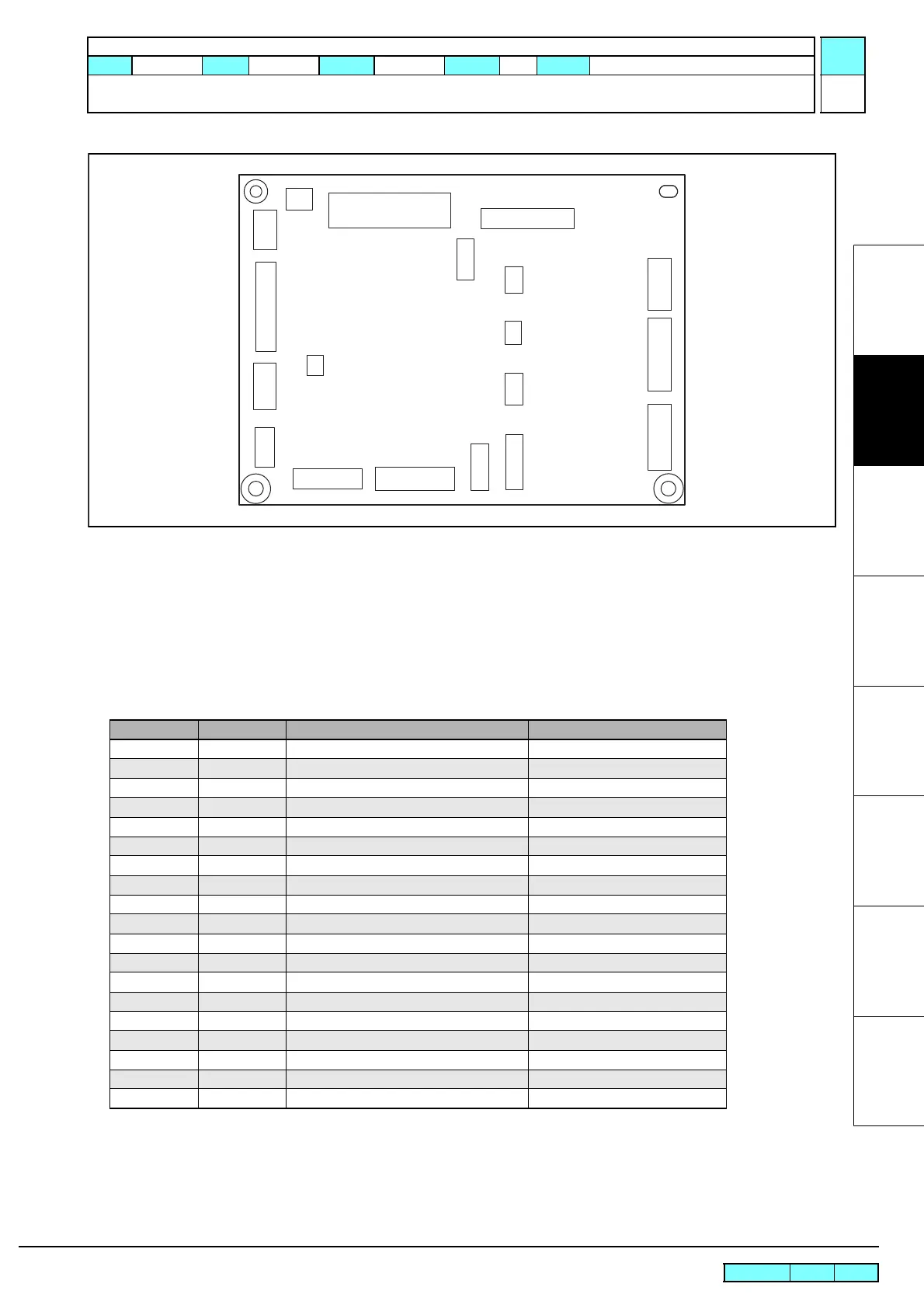
Outline
Board name: Station PCB Assy
Is located on the side panel inside the right cover.
The pump motor, vacuum fan, paper sensor, Y-origin sensor and other main body control I/Os are connected to this PCB.
List of connectors
CN No Pin Connected to: Remarks
CN1 40 Main PCB Assy
CN2 20 AUX.
CN3 24 Keyboard
CN4 4 Sleep Switch
CN5 2 AUX.
CN6 4 Washing Cartridge, ID Contact PCB Assy
CN7 2 P Head Lock Solenoid
CN8 18 External Unit Output Take-up, Exhaust Fan, Dry Fan
CN9 10 Vacuum Fan
CN10 4 Washing Cartridge Sensor
CN11 - Not used
CN12 7 Paper Sensor (R)
CN13 9 Clamp Sensor, Y-origin Sensor
CN14 4 AUX.
CN15 3 AUX.
CN16 3 AUX.
CN17 8 Wiper Unit Wiper Motor, Wiper-origin
CN18 9 Pump Motor
CN19 6 AUX.
CN1
CN20
CN5
CN8 CN9
CN12
CN2
CN2
CN13
CN14
CN15
CN16
CN17
CN18
CN19
CN6
CN10
CN7
CN4
 Loading...


