© 2009 MIMAKI ENGINEERING CO.,LTD.
2.3.7 P.1
1
2
3
4
5
6
7
8
R.1.1
Maintenance Manual > Electrical Parts > Circuit Board Specifications > X-axis Motor Relay PCB Assy
Model CJV30/TPC Issued 2008.08.04 Revised 2008.09.17 F/W ver. 1.20 Remark
1.1
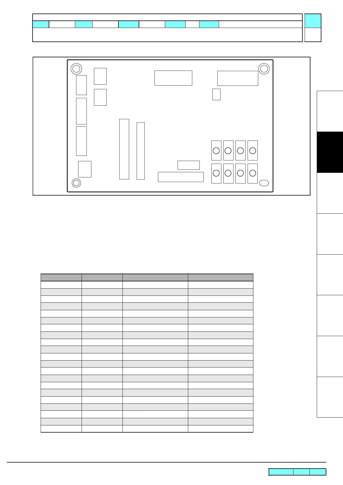
2.3.7 X-axis Motor Relay PCB Assy
Outline
Board name: X-axis Motor Relay PCB Assy
Is located on the back of the ink cartridge unit inside the left cover.
The solenoids of the 8 ink cartridges, ID, ink near end sensor, cartridge sensor, LED PCB assy, cover sensor,
maintenance cover sensor, etc. are connected to it.
List of connectors
CN No Pin Connected to: Remarks
CN1 28 Main PCB Assy
CN2 20 LED PCB Assy
CN3 30 Main PCB Assy
CN4 4 Ink Cartridge 1
CN5 4 Ink Cartridge 2
CN6 4 Ink Cartridge 3
CN7 4 Ink Cartridge 4
CN8 4 Ink Cartridge 5
CN9 4 Ink Cartridge 6
CN10 4 Ink Cartridge 7
CN11 4 Ink Cartridge 8
CN12 16 Ink Solenoid (1-8)
CN13 18 Ink ID (1-8)
CN14 6 X-axis Motor Encoder
CN15 5 Not equipped AUX.
CN16 2 AUX.
CN17 2 AUX.
CN18 3 AUX. AUX.
CN19 6 Not equipped AUX.
CN20 2 AUX. AUX.
CN21 2 AUX.
1234
5678
CN1
CN14
CN21
CN15
CN16
CN17
CN2
CN19
CN20
CN4CN5CN6CN7
CN8CN9CN10CN11
CN12
CN13
CN3
CN18
CN18
 Loading...


