© 2009 MIMAKI ENGINEERING CO.,LTD.
2.3.8 P.1
1
2
3
4
5
6
7
8
R.1.1
Maintenance Manual > Electrical Parts > Circuit Board Specifications > Ink Slider PCB Assy
Model CJV30/TPC Issued 2008.08.04 Revised 2008.09.17 F/W ver. 1.20 Remark
1.1
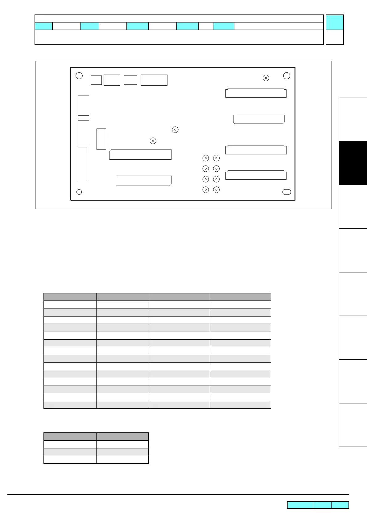
2.3.8 Ink Slider PCB Assy
Outline
Board name: Ink Slider PCB Assy
Is located on the top of the print part slider.
FFC from main PCB assy is connected to this PCB to relay signals to print head. In addition, the encoder PCB assy,
head height sensor, etc. are connected to this PCB.
List of connectors
Test poi nt
CN No Pin Connected to: Remarks
CN1 30 Main PCB Assy IO control
CN2 50 Main PCB Assy Head control
CN3 30 Main PCB Assy Power source
CN4 30 Main PCB Assy COM waveform
CN5 35 Print Head
CN6 31 Print Head
CN7 4 AUX.
CN8 6 AUX.
CN9 3 Head Height Sensor
CN10 5 Linear Encoder PCB Assy
CN11 2 AUX.
CN12 3 AUX.
CN13 11 Head Memory PCB Assy Head memory
CN14 6 None AUX.
Terminal name Application
TP5 VBS (+8V)
TP6-13 COM1-8 (A-H)
TPG3, 5 GND
TP5
TPG5
TPG3
TP6
TP8
TP11
TP10
TP7
TP9
TP12
TP13
CN1
CN2
CN3
CN5
CN8CN12CN11
CN9
CN7
CN10
CN13
CN14
CN6
CN4
 Loading...


