α
2 Simple Application Controllers
Key, System Bit and Function Block Lists 10
ENG-49
ENG
10.2 System Bit Lists
There is the system bit controlled by system and the control bit to control from user program.
10.2.1 System Bit Lists
10.2.2 Control Bit Lists
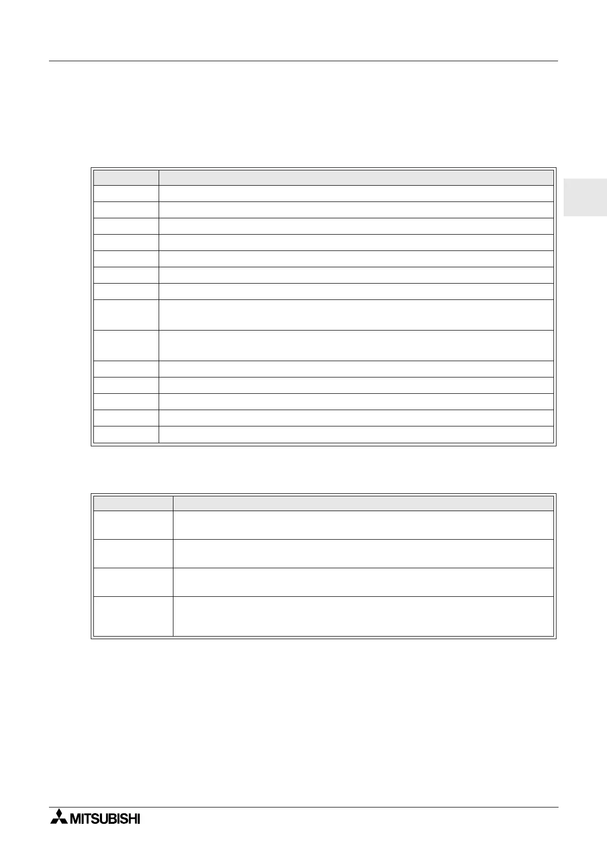
*1 When both N02 and N03 are ON and hence the back light is “ON” because N03 is given
the priority.
Table 10.2: System Bit Lists
System Bit Description
M01 Always “ON”
M02 Always “OFF”
M03 Alternate - 0.5 seconds “ON”, 0.5 seconds “OFF”
M04 “ON” when Real Time Clock data error occurs
M05 “ON” when Summer time schedule is activated
M06 “ON” when communication Error of AS-interface occurs
M07 “ON” when communication Error by AS-interface power failure occurs
M08
ONwhenturnStopmodeturnstoRunmodeinthe
α
2 Series. The ON signal acts as a
pulse output and then turns OFF.
M09
OFF when turn Stop mode turns to Run mode in the
α
2 Series. The OFF signal acts
as a pulse output and then turns ON.
M10 Reserved
M11 Reserved
M12 “ON” when CD (DCD) signal is turned ON (receiving CD signal from modem)
M13 “ON” when it is possible to access the GSM network.
M14
“ON” when the
α
2seriesisaccessedviaGSM.
Table 10.3: Control Bits
Control Bit Description
N01
ON: Disconnected to AS-interface network
OFF: Connect to AS-interface network
N02
*1
ON: The back light is “OFF”inLCD.
OFF: The back light is controlled by the “Light Time” setting in Menu.
N03
*1
ON: The back light is “ON” in LCD.
OFF: The back light is controlled by the “Light Time” setting in Menu.
N04
ON: The user screen is controlled by the setting of “Display Manager” with AL-
PCS/WIN-E.
OFF: The user screen is controlled by user program.
 Loading...


