2205B0JE-DA-J-N_2014.05.
2 Structure and Specifications of the Compressor
Screw Compressor J-series 2.3 Compressor Specifications
2-8
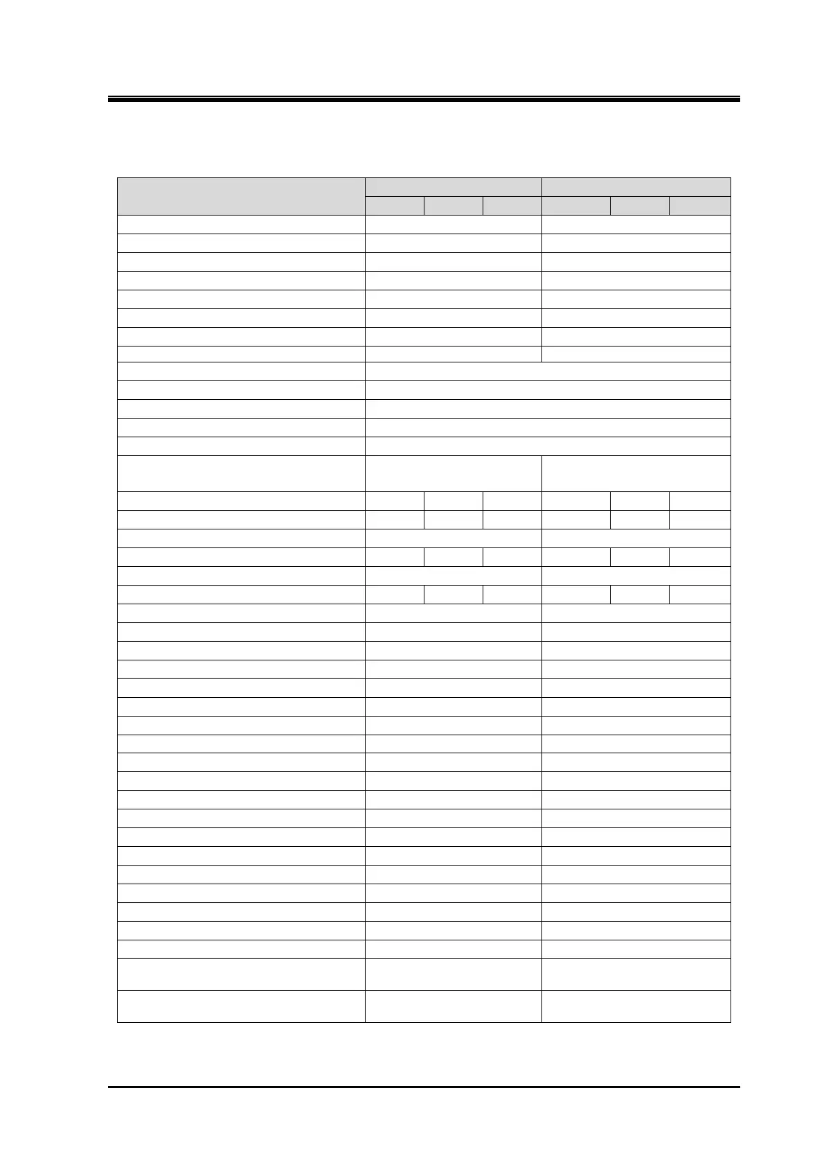
Table 2-5 170J and 220J-series Outer Dimensions Table (Standard Specification)
Unit(mm)
Item
170J 220J
S M L S M L
1: Suction ANSI #300 5”(8-M20) ANSI #300 8”(12-M22)
2: Discharge ANSI #300 3”(8-M20) ANSI #300 5”(8-M20)
3: Oil supply (Discharge-side) ANSI #300 1”(4-M16) ANSI #300 1”(4-M16)
4: Oil supply (Suction-side) Rc1/2 Rc3/4
5: Oil Injection Rc1/2 Rc3/4
6: E-port ANSI #300 1”(4-M16) ANSI #300 1 1/2”(4-M20)
7: I-port ANSI #300 3/4”(4-M16) ANSI #300 3/4”(4-M16)
8: F-injection (Option) Rc1/2 Rc3/4
9: Hydraulic cylinder oil supply Rc1/2
10:Hydraulic cylinder oil drain Rc1/2
11:Hydraulic cylinder oil return Rc1/2
12:Unloader indicator connect PF 3/4
13:Vi-sensor connect connector
14:The leg hole for securing the
compressor
4-φ19 4-φ23
L1 1358 1413 1485 1680 1752 1845
L2 360 415 487 459 531 624
L3 151 190
L4 285 340 412 357 429 522
L5 85 132
L6 315 370 442 395 467 560
L7 385 482
L8 20 70
L9 75 105
L10 100 114
L11 90 100
H1 550 700
H2 245 300
H3 130 160
H4 415 520
H5 285 362
H6 110 140
H7 56 71.5
W1 580 721
W2 210 240
W3 420 480
W4 275 340
W5 225 285
W6 92(F rotor side) 86(M rotor side)
W7 64 83
W8 16
0
20
0
-0.043
-0.052
D1 52
+0.012
67
+0.012
-0.007
-0.007
 Loading...


