Chapter 7 Counters
X Series User Manual 7-34 ni.com
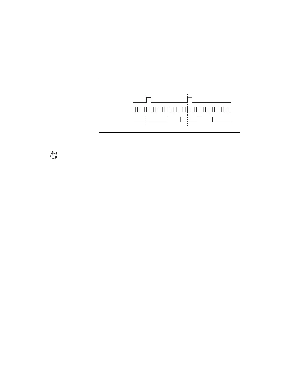
Figure 7-32 shows the same pulse train with
CO.EnableInitalDelayOnRetrigger set to the default False.
Figure 7-32. Retriggerable Single Pulse Generation with
Initial Delay on Retrigger Set to False
Note
The minimum time between the trigger and the first active edge is two ticks of the
source.
For information about connecting counter signals, refer to the Default
Counter/Timer Pinouts section.
Continuous Pulse Train Generation
This function generates a train of pulses with programmable frequency and
duty cycle. The pulses appear on the Counter n Internal Output signal of the
counter.
You can specify a delay from when the counter is armed to the beginning
of the pulse train. The delay is measured in terms of a number of active
edges of the Source input.
You specify the high and low pulse widths of the output signal. The pulse
widths are also measured in terms of a number of active edges of the Source
input. You also can specify the active edge of the Source input (rising or
falling).
The counter can begin the pulse train generation as soon as the counter is
armed, or in response to a hardware Start Trigger. You can route the Start
Trigger to the Gate input of the counter.
You also can use the Gate input of the counter as a Pause Trigger (if it is not
used as a Start Trigger). The counter pauses pulse gener
ation
when the
Pause Trigger is active.
SOURCE
GATE
(Start Trigger)
OUT
5 3 2 3
Counter
Load Values
4 3 21 0 210 4 3 210210
Artisan Technology Group - Quality Instrumentation ... Guaranteed | (888) 88-SOURCE | www.artisantg.com

 Loading...


