Chapter 9 Digital Routing and Clock Generation
© National Instruments 9-5 X Series User Manual
In a PXI Express system, the RTSI bus is replaced by the PXI and
PXI Express trigger signals on the PXI Express backplane. This bus can
route timing and trigger signals between several functions on as many as
seven DAQ devices in the system.
USB devices do not support the RTSI bus.
RTSI Connector Pinout
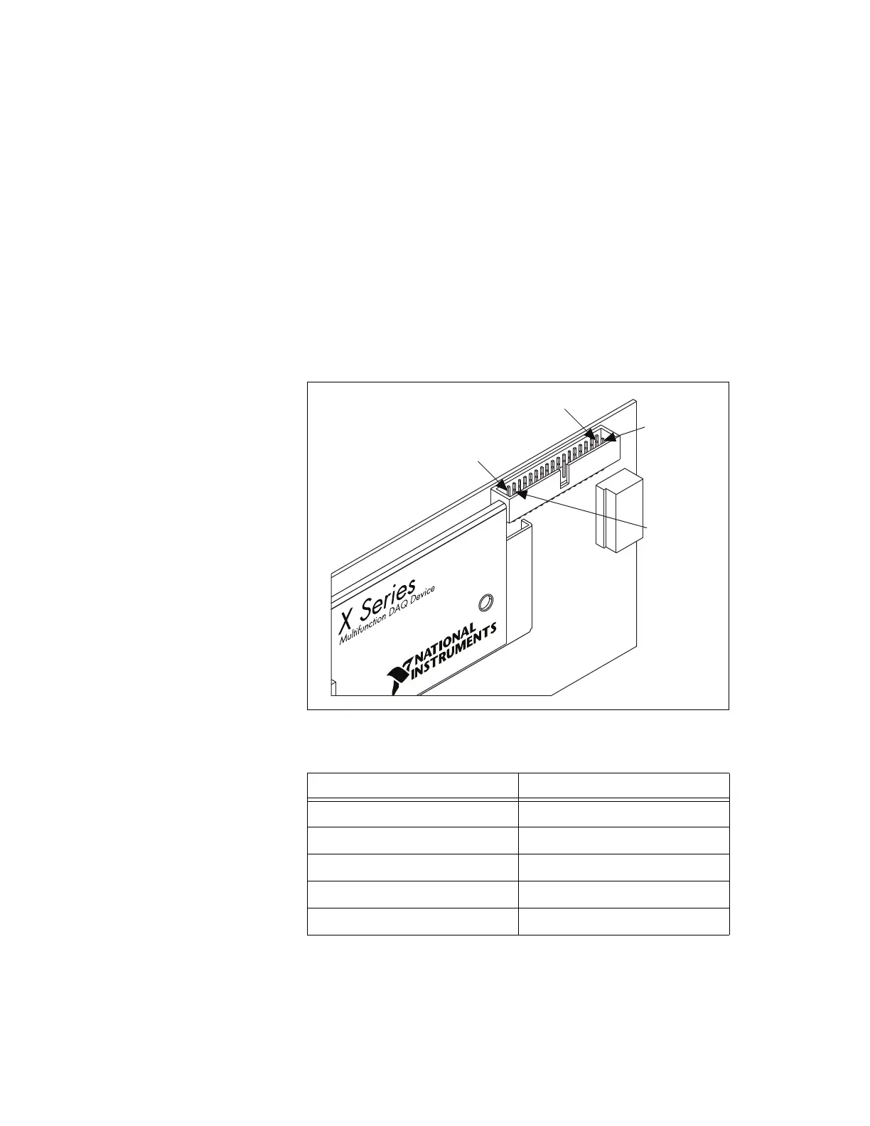
(NI PCIe-632x/634x/635x/636x Devices) Figure 9-2 shows the RTSI connector
pinout and Table 9-1 describes the RTSI signals.
Figure 9-2. PCI Express X Series Device RTSI Pinout
Table 9-1. RTSI Signals
RTSI Bus Signal Terminal
RTSI 7 34
RTSI 6 32
RTSI 5 30
RTSI 4 28
RTSI 3 26
Te r mi nal 1
Terminal 2
Te r mi nal 34
Te r mi nal 33
Artisan Technology Group - Quality Instrumentation ... Guaranteed | (888) 88-SOURCE | www.artisantg.com

 Loading...


