Chapter 8 PFI
© National Instruments 8-5 X Series User Manual
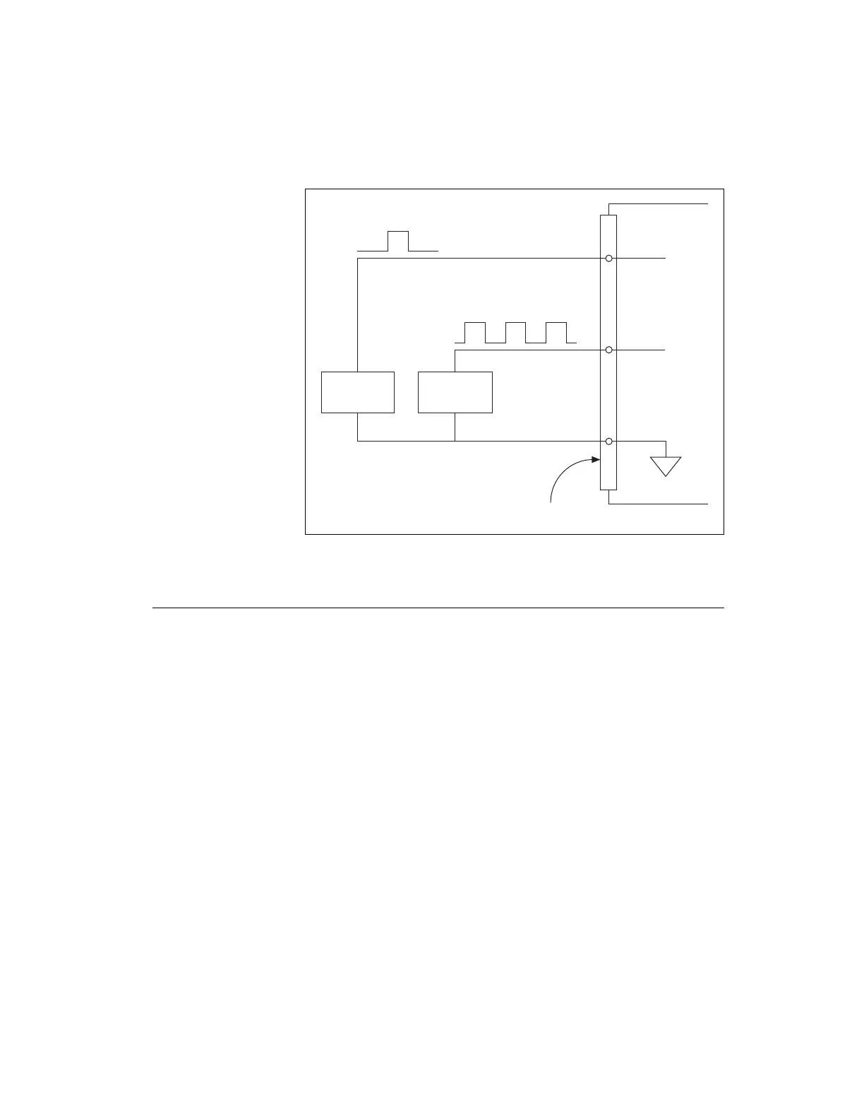
Figure 8-2. PFI Input Signal Connections
PFI Filters
You can enable a programmable debouncing filter on each PFI, RTSI,
PXI_STAR, or PXIe-DSTAR<A,B> signal. When the filters are enabled,
your device samples the input on each rising edge of a filter clock. X Series
devices use an onboard oscillator to generate the filter clock.
The following is an example of low to high transitions of the input signal.
High-to-low transitions work similarly.
Assume that an input terminal has been low for a long time. The input
terminal then changes from low to high, but glitches several times. When
the filter clock has sampled the signal high on N consecutive edges, the low
to high transition is propagated to the rest of the circuit. The value of N
depends on the filter setting; refer to Table 8-1.
PFI 0
Source
PFI 2
Source
X Series Device
D GND
PFI 2
PFI 0
I/O Connector
Artisan Technology Group - Quality Instrumentation ... Guaranteed | (888) 88-SOURCE | www.artisantg.com

 Loading...


