General
Pipe installation must be carried out in accordance with
current regulations. See manual for compatible NIBE
air/water heat pump for installation of the heat pump.
NOTE
The heating medium side and the domestic hot
water side must be fitted with the necessary
safety equipment in accordance with the applic-
able regulations.
The pipe dimension should not be less than the recommen-
ded pipe diameter according to the table. However, each
system must be dimensioned individually to manage the
recommended system flows.
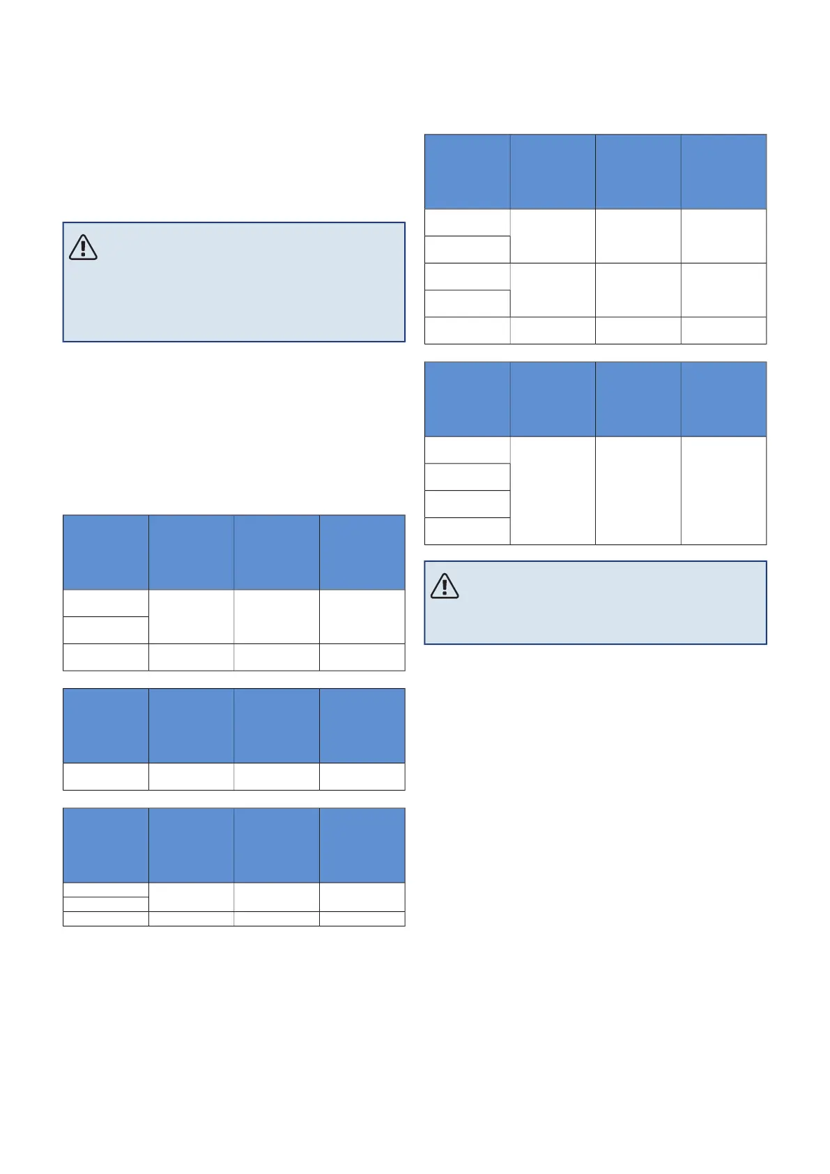
MINIMUM SYSTEM FLOWS
The installation must be dimensioned at least to manage
the minimum defrosting flow at 100% pump operation, see
table.
Minimum re-
commended
pipe dimen-
sion (mm)
Minimum re-
commended
pipe dimen-
sion (DN)
Minimumflow
during de-
frosting
(100% pump
speed (l/s)
Air/water
heat pump
22200.19
AMS 10-6/
HBS 05-6
AMS 10-8/
HBS 05-12
22200.29AMS 10-12/
HBS 05-12
Minimum re-
commended
pipe dimen-
sion (mm)
Minimum re-
commended
pipe dimen-
sion (DN)
Minimumflow
during de-
frosting
(100% pump
speed (l/s)
Air/water
heat pump
22200.19
AMS 20-6/
HBS 20-6
Minimum re-
commended
pipe dimen-
sion (mm)
Minimum re-
commended
pipe dimen-
sion (DN)
Minimumflow
during de-
frosting
(100% pump
speed (l/s)
Air/water
heat pump
22200.19
F2040-6
F2040-8
22200.29F2040-12
Minimum re-
commended
pipe dimen-
sion (mm)
Minimum re-
commended
pipe dimen-
sion (DN)
Minimumflow
during de-
frosting
(100% pump
speed (l/s)
Air/water
heat pump
22200.27
F2120-8
(1x230V)
F2120-8
(3x400V)
28250.35
F2120-12
(1x230V)
F2120-12
(3x400V)
28250.38
F2120-16
(3x400V)
Minimum re-
commended
pipe dimen-
sion (mm)
Minimum re-
commended
pipe dimen-
sion (DN)
Minimumflow
during de-
frosting
(100% pump
speed (l/s)
Air/water
heat pump
28250.32
S2125-8
(1x230V)
S2125-8
(3x400V)
S2125-12
(1x230V)
S2125-12
(3x400V)
NOTE
An undersized system can result in damage to the
product and lead to malfunctions.
VVM S320 together with a compatible NIBE air/water heat
pump (See section Outdoor modules.) constitutes a complete
installation for heating and hot water.
The system requires the radiator circuit to be designed for
a low temperature heating medium. At lowest dimensioned
outdoor temperature, the highest recommended temperat-
ures are 55 °C on the supply line and 45 °C on the return
line, but VVM S320 can handle up to 70 °C.
Overflow water from the safety valve goes via an overflow
cup to a drain so that hot water splashes cannot cause in-
jury. The entire length of the overflow water pipe must be
inclined to prevent water pockets, and must also be frost-
proof. The mouth of the overflow water pipe must be visible
and not located close to electrical components.
NIBE recommends installing VVM S320 as close to the heat
pump as possible for the optimum comfort. For further in-
formation about the location of various components, see
section "Installation alternatives" in this manual.
13Chapter 4 | Pipe connectionsNIBE VVM S320
Pipe connections
 Loading...