Connections
TERMINAL BLOCKS
The following terminal blocks are used on the base board
(AA2).
-X29
-X28
1 0-5V
2 +5V
3 AUX1
4 AUX2
5 AUX3
6 AUX4
7 AUX5
8 AUX6
9 AUX7
10 AUX8
11 AUX9
12 BT25
1
1
2
3
2
3
4
5
6
7
8
9
10
11
12
GND
+12V
B
A
OT+
OT−
0-5V
PWM0
PWM1
CPU
EXT COM
INT COM
ERROR
POWER
+5V
GND
BE1
BE2
BE3
K10
-X27
NO
O
NC
AUX-RELAY
13 BT50
14 BT1
-X30
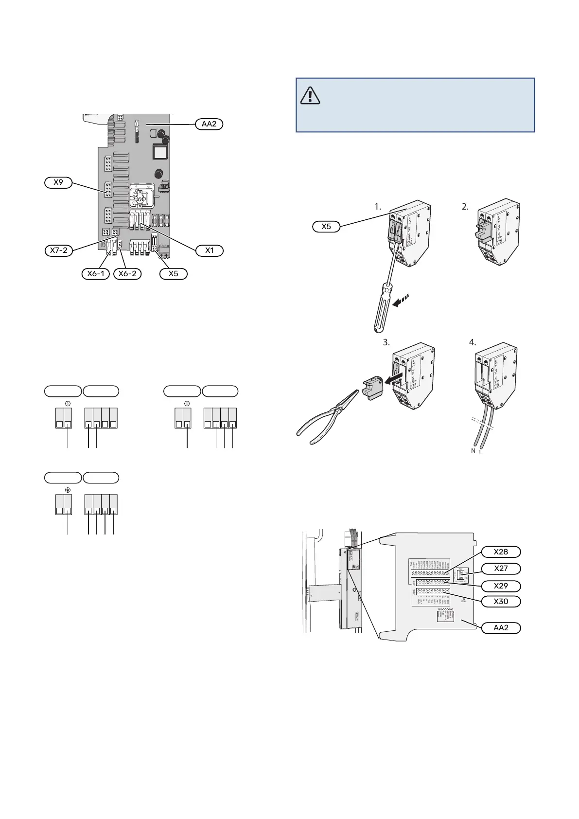
POWER CONNECTION
Supply voltage
Enclosed cable for incoming supply electricity is connected
to terminal block X1 and X6-1 on the PCB (AA2).
Connection 3x230V
AA2-X1
PE (L2) L1 L2 L3
1 2 3 4
AA2-X6-1
Connection 1x230V
AA2-X1
PE N L (L) (L)
1 2 3 4
AA2-X6-1
Connection 3x400V
AA2-X1
AA2-X6-1
PE N L1 L2 L3
1 2 3 4
Tariff control
If the voltage to the indoor module is lost for a certain period,
this must be blocked simultaneously via the selectable in-
puts, see section "Selectable in/outputs – Possible selections
for AU inputs". Compressor blocking must be carried out
either on the indoor module or on the air/water heat pump,
not on both at the same time.
External control voltage for the control
system
NOTE
Mark up any junction boxes with warnings for ex-
ternal voltage.
Control voltage (230 V ~ 50Hz) connects to AA2:X5:N, X5:L
and X6-2 (PE).
When connecting external control voltage, remove the
bridges from terminal block X5.
EXTERNAL CONNECTIONS
Connect external connections on terminal blocks X28, X29
and X30 on the base board (AA2).
-X29
-X28
1 0-5V
2 +5V
3 AUX1
4 AUX2
5 AUX3
6 AUX4
7 AUX5
8 AUX6
9 AUX7
10 AUX8
11 AUX9
12 BT25
1
1
2
3
2
3
4
5
6
7
8
9
10
11
12
GND
+12V
B
A
OT+
OT−
0-5V
PWM0
PWM1
CPU
EXT COM
INT COM
ERROR
POWER
+5V
GND
BE1
BE2
BE3
K10
-X27
NO
O
NC
A
UX-RELAY
13 BT50
14 BT1
-X30
21Chapter 5 | Electrical connectionsNIBE VVM S320
 Loading...