General
All electrical equipment, except the outdoor sensors, room
sensors and the current sensors are ready connected at the
factory.
• Disconnect VVM S320 before insulation testing the house
wiring.
• If the building is equipped with an earth-fault breaker,
VVM S320 should be equipped with a separate one.
• VVM S320 must be installed via an isolator switch. The
cable area has to be dimensioned based on the fuse rating
used.
• If a miniature circuit breaker is used, this must have at
least triggering characteristic "C". See section "Technical
specifications" for fuse size.
• Use a screened cable for communication with the heat
pump.
• To prevent interference, sensor cables to external connec-
tions must not be laid close to high voltage cables.
• The minimum area of communication and sensor cables
to external connections must be 0.5 mm² up to 50 m, for
example EKKX, LiYY or equivalent.
• For an electrical wiring diagram for VVM S320, see the
"Technical specifications" section.
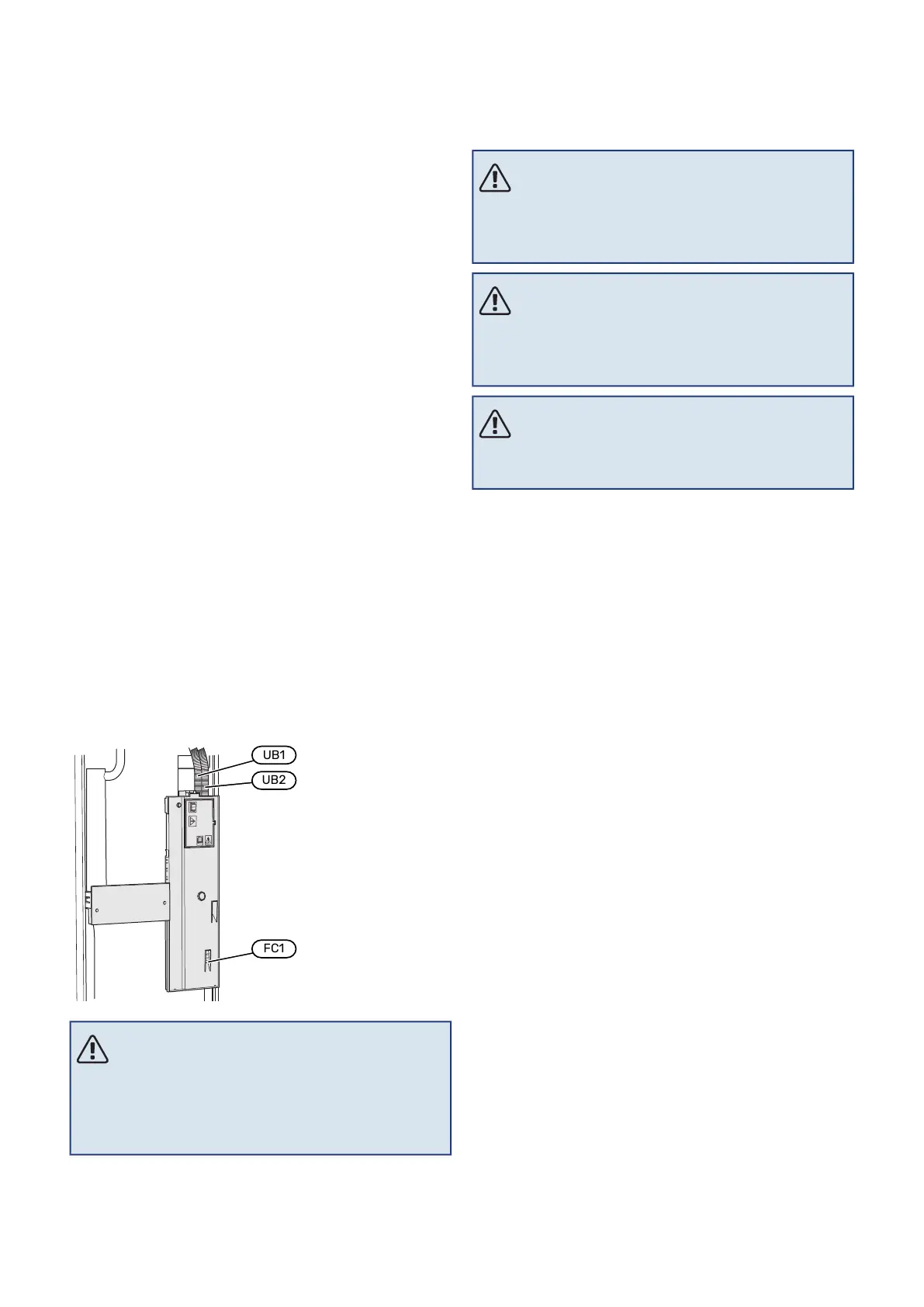
• When cable routing in VVM S320, the cable grommets (UB1
and UB2) must be used.
NOTE
Electrical installation and any servicing must be
carried out under the supervision of a qualified
electrician. Disconnect the current using the cir-
cuit breaker before carrying out any servicing.
NOTE
If the supply cable is damaged, only NIBE, its ser-
vice representative or similar authorised person
may replace it to prevent any danger and damage.
NOTE
Check the connections, main voltage and phase
voltage before the machine is started to prevent
damage to the indoor module's electronics.
NOTE
Do not start the system before filling up with wa-
ter. Components in the system could be damaged.
MINIATURE CIRCUIT-BREAKER
The operating circuit in VVM S320 and some of its internal
components are fused internally by a miniature circuit
breaker (FC1).
(Only applies to 1x230 V and 3x230 V.)
19Chapter 5 | Electrical connectionsNIBE VVM S320
Electrical connections
 Loading...