Chapter 4 Functions and Operations of the Devices
41
8
Stages
8.1
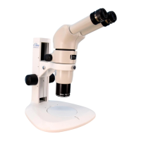
P-SXY64 XY Stage
This stage shifts the glass plate in the X and Y directions when
the X/Y shift knobs are turned. Attach this stage instead of the
base.
The height of the stage is 36.7 mm.
The glass plate measures 215 mm x 154 mm x 5 mm and is
detachable.
Stage adapters for AZ are usable with the stage and a 45-mm dia.
filter can be slotted into the optical-path hole on the lower board o
the stage.
[Usable stands]
P-PS32 Plain Stand
P-DSL32 LED Diascopic Illumination Stand
P-DSF32 Fiber Diascopic Illumination Stand
P-SXY64 XY Stage
XY stroke of the stage with the X/Y shift knob and stroke per knob rotation
X: 150 mm; 37.5 mm per rotation
Y: 65 mm (from the optical path, 50 mm towards the front, 15 mm towards the rear); 24.1 mm per rotation
Load weight
5 kg or less
8.2
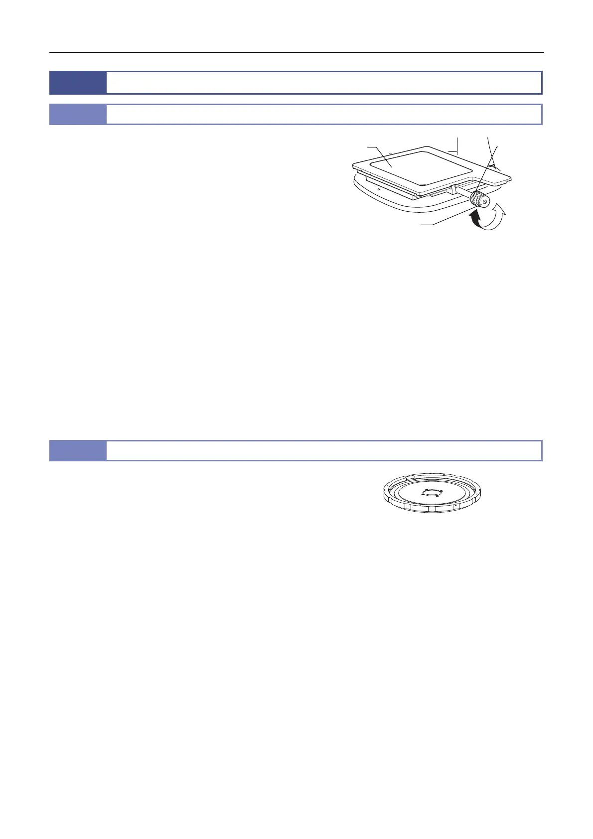
C-SSL DIA Sliding Stage
This stage is movable in the range of ±19 mm in the radial
direction by pressing the stage’s side.
The height of the stage is 11.5 mm.
ttach the stage to the position where the stage plate was removed
from the base. Attach the removed stage plate on the C-SSL DIA
sliding stage.
[Usable stands]
P-PS32 Plain Stand
P-DSL32 LED Diascopic Illumination Stand
P-DSF32 Fiber Diascopic Illumination Stand
C-DS Dia Illumination Stand
C-SSL DIA Sliding Stage
Stage Y shift
knob
Stage X
shift knob
Glass plate
 Loading...