100 DAA2 & DAX — P/N 53265:A1 8/24/2011
DAA Digital Audio Amplifiers Installation
2. Select and punch open the appropriate cabinet knock-outs. (For selection guidelines, see
“UL Power-limited Wiring Requirements” on page 119.)
3. Using the keyholes, mount the backbox on the two bolts.
4. Mark the location of the two lower holes, remove backbox and drill the mounting holes.
5. Mount the backbox over the top two screws, then install the remaining fasteners. Tighten
all fasteners securely.
6. Feed wires through appropriate knockouts.
7. Install DAA according to the following instructions before installing the door per the
CAB-4 Series Cabinet Installation Document.
The DAA fills one row of any CAB-4 series cabinet.
CAB-3 Cabinets
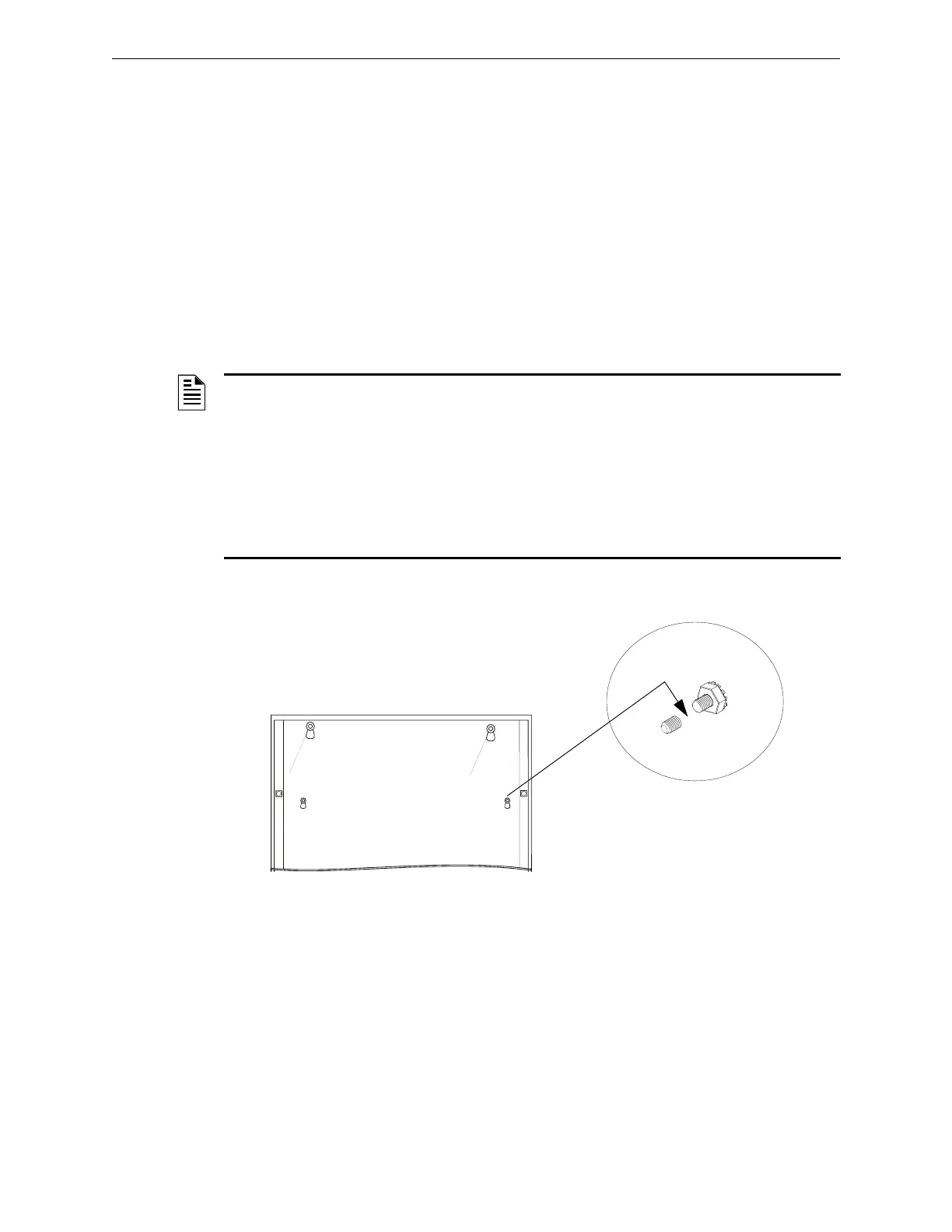
Figure C.6 Using Older Backboxes
NOTE: The DAA is compatible with the CAB-3 Series backboxes. However, when installing the
DAA in a CAB-3 Series or gray CAB-4 Series non-ONYX backboxes, the stud indicated in
Figure C.6 must be shortened to allow room for the TB12 connector.
Stud height must not exceed. Gray versions of the CAB-4 Series backboxes and all CAB-3 Series
backboxes have studs that require shortening.
WARNING:
• Do not cut without nut in place to protect threading.
• Remove all electronics from the backbox prior to cutting to avoid damage to electronics.
• Wear protective eye covering.
Cut stud with
metal-cutting
tool.
Verify stud height and cut if stud
exceeds 0.375 in. (9.525 mm). See
note and warning above.
DAACABretro.eps
DAA row in backbox
DAA_CAB3studct.wmf
Procedure:
1. Prior to DAA installation, apply nut to
mounting stud to protect threading.
2. Cut stud to proper length.
3. Loosen nut slightly to allow DAA chassis
installation, then tighten nut securely.
 Loading...