70 DAA2 & DAX — P/N 53265:A1 8/24/2011
BDA Backup Digital Amplifiers Installation
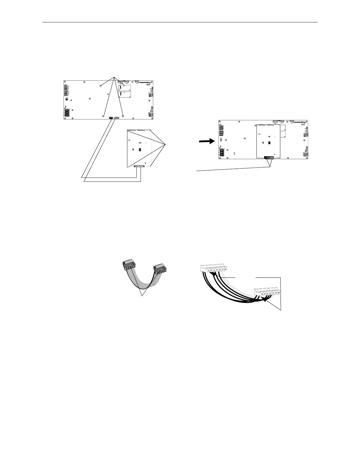
4.4.2 DAX
Figure 4.3 shows the installation of a BDA-25/70V onto a DAX amplifier. The BDA may be
programmed and wired for backup.
Figure 4.3 BDA-25V/70V Installation, DAX
4.4.3 BDA Power and Control Cables
Figure 4.4 BDA Control and Power Cables
1. Attach four standoffs
at locations indicated.
2. Align BDA
over standoffs.
Attach with four
screws.
3. Attach power
harnesses
(included with
BDA - refer to
Figure 4.4):
Power and Control
Harness
Connections
BDA
DAX
J2 J1
J7
J6
• J1 on BDA to J6 on DAX
• J2 on BDA to J7 on DAX
BDA Control cable,
p/n 75690
Align tab with
notch in board
connector.
Tab
BDA Power cable,
p/n 75689
Align cable connectors
over spaces and pins.
Align where
there is no pin.
 Loading...