DAA2 & DAX — P/N 53265:A1 8/24/2011 111
Installation DAA Digital Audio Amplifiers
Programming must reflect whether the riser contains modules or not. Use VeriFire Tools to set
these parameters.
1. “Install FTM” selected - Firefighter Telephones must be wired to the output of the FTM
modules or an XPIQ. The telephone points will be SLC addresses.
2. “Install FTM” not selected - Firefighter Telephones must be wired directly to the DAA
FFT riser. The telephone point will be a DAA phone point. (AxT; where x = the DAA
address)
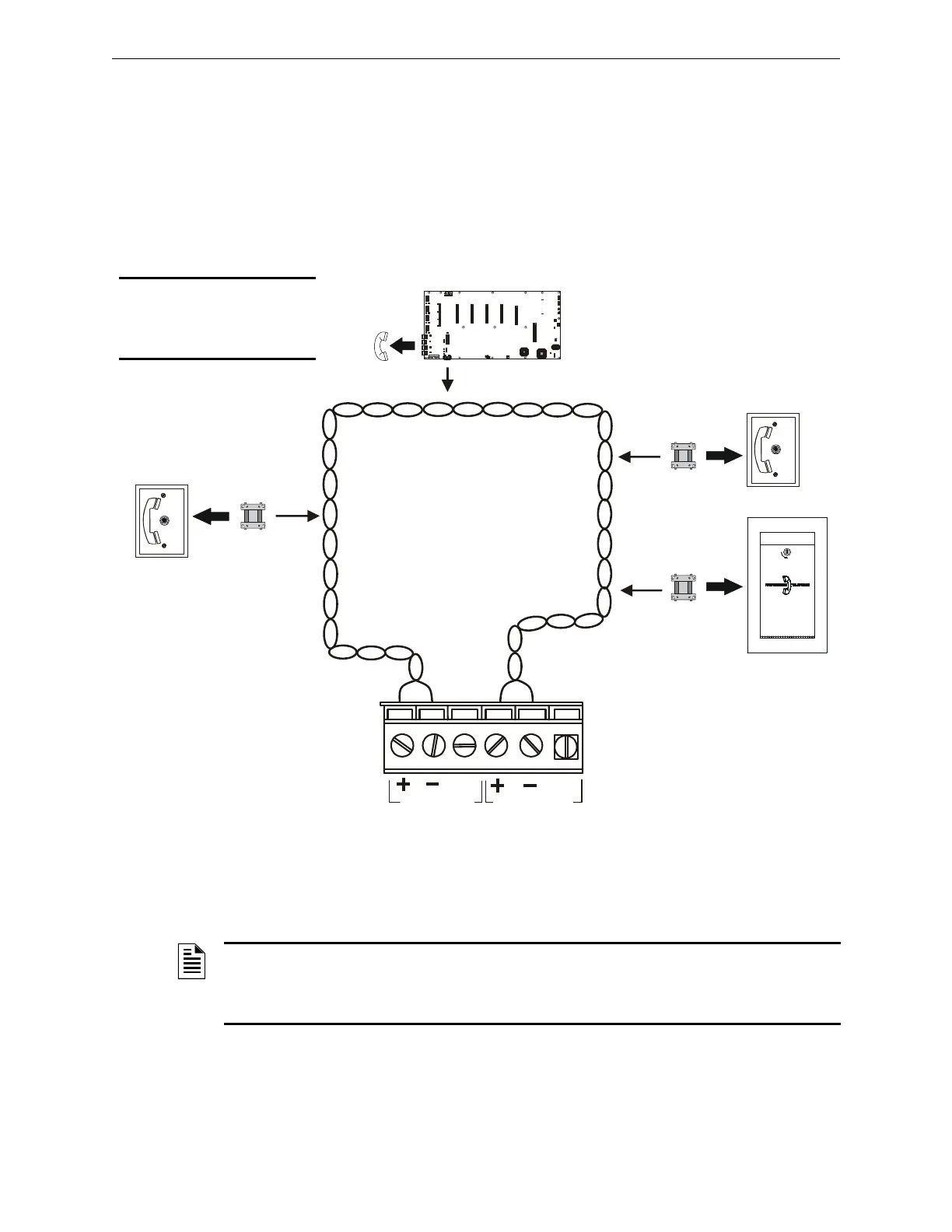
Figure C.20 FFT Riser (Class A Example)
An FHS firefighter handset may be used with the phone jacks in Figure C.20. For a description of
the DVC firefighter telephone network operation, refer to the FFT appendix in the DVC Digital
Voice Command manual..
Auxiliary Inputs A and B
The DAA provides two analog audio connections. One or the other may be used, not both.
TB1 TB2
TB3
TB4
TB5
TB6 TB7
TB8
J7 J6
J11 J12
J13
TB10
SW4
DETECTION
EARTH
FAULT
GEN TBL
DISABLED
ENABLED
P6
P5
P4
P3
P2
P1
Low Le vel
Backup IN
Remote
Out
BCKGND
MUSIC
Remote
In
High Level
Backup IN
High Level
Backup OUT
Low Le vel
Backup OUT
J9
XPIQ-PS Control Cable
XPIQ-PS Power
EXT TRBL I N
SW3
SW2
PHONE
1 AND 2
PHONE
3 AND 4
CHGTRBL
Phone 4 TRBL
Phone 3 TRBL
Phone 2 TRBL
Phone1 TRBL
Riser TRBL
TRBL
TRBL
TRBL
TRBL
SPKR1
SPKR2
SPKR3
SPKR4
BATTRBL
A.C.Fail
J1
J2
J10
J4
J5
J8
Phone 1
Phone 2
Phone 3
Phone 4
Spkr1
Spkr2
Spkr3
Spkr4
TB9
2 X 2W
2 X 2W
1 X 4W
1 X 4W
PHONE/NAC RISER
XPIQ-CA Option
SHLD - PH + SHLD - PH +
+ OUT - SHLD + OUT - SHLD
+ OUT - SHLD + OUT - SHLD
CONTROL/COMM
AUDIO IN
AMPLIFIER #4
AMPLIFIER # 3
AMPLIFIER # 2
AMPLIFIER #1
1 2
1 2 3 4 5 6
S - +
S - + S - + S - +
1 2 3 1 2 3 1 2 3 1 2 3
1 2 31 2 3 1 2 3 1 2 3
5
6
7
8
4
NOTIFIER XPIQ-MBPCA REV.
PHONE JACK
FIREFIGHTER’S
PHONE JACK
SHLD
Telephone
Control Module
XPIQ
FPJ or RPJ-1
Firefighter
Phone Jack
DVCFFTriser.wmf
DAA
AFAWS Fire
Alarm Warden
Station
TB7
Max wiring resistance (including
individual telephone zone to last
handset) permitted is 50 ohms. 10,000
ft. (3048 m) max. wiring distance at 14
AWG to last handset.
14-18 AWG
twisted-pair
recommended
Telephone
Control Module
Telephone
Control Module
FPJ or RPJ-1
Firefighter
Phone Jack
NOTE: If an FFT riser is not
programmed for modules,
telephone modules, as well
as the XPIQ, are not options.
NOTE: Digital audio software Version 2.0 and above does not support FFT risers on DVC or DAA
PCA boards. Refer to Figure C.2 on page 94 for how to determine DAA board type. Refer to the
DVC Digital Voice Command manual for how to distinguish PCA from PCB board types. Check
VeriFire or an appropriate network display to determine the software version.
 Loading...