DAA2 & DAX — P/N 53265:A1 8/24/2011 17
Description DAA2 Digital Audio Amplifiers
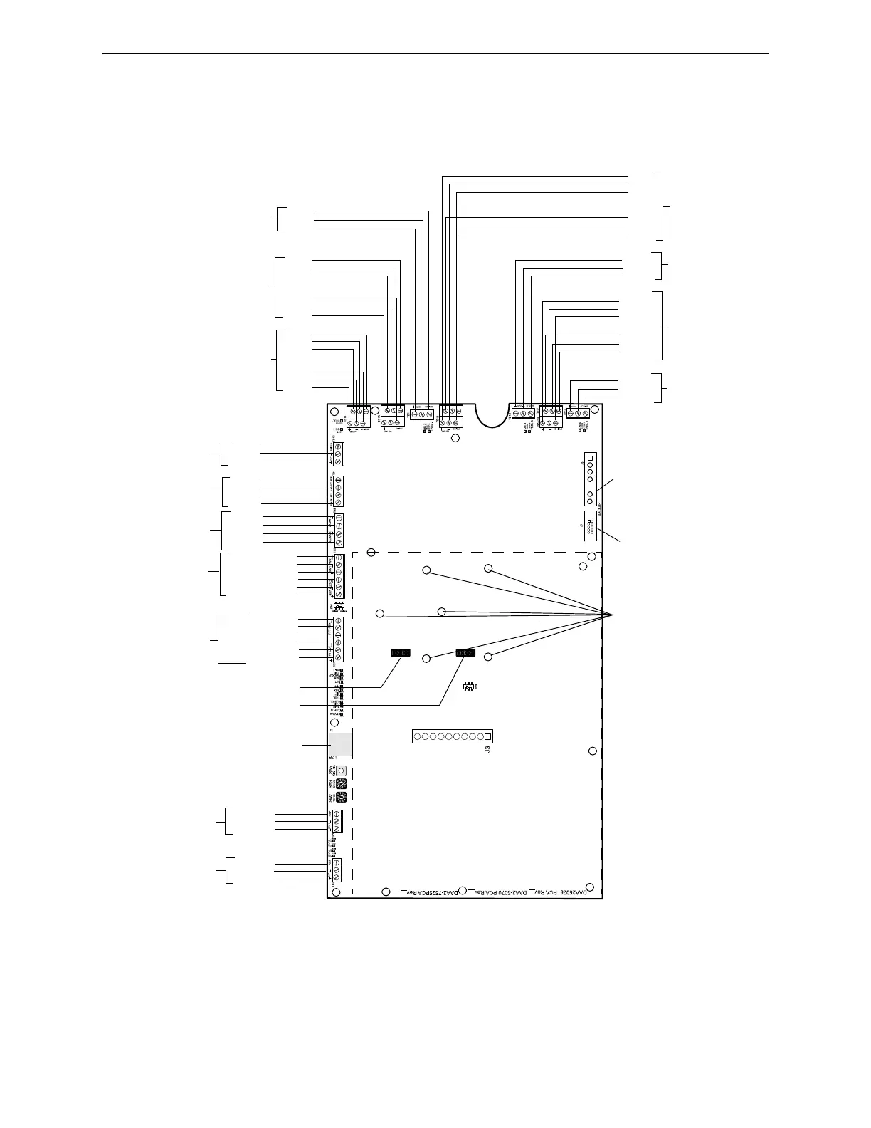
2.1.3 DAA2 Layout
Connection Locations
A DAA2 is comprised of two boards; a larger rear board, and a smaller front power supply board.
Figures 2.1 and 2.2 below show the layout.
Figure 2.1 DAA2 Rear Board
OUT 4 +
OUT 4 -
SHIELD
+
-
SHIELD
+
-
SHIELD
SHIELD
+
-
SHIELD
SHIELD
OUT1 -
+
-
SHIELD
-
+
OUT1 +
SHIELD
OUT3 +
OUT3 -
BDA Power J6
BDA Control J5
OUT 3
TB12
See p.33
BKUP3
TB16
See p.37
OUT 4
TB13
See p.33
BKUP4
TB17
See p.37
OUT 1
TB10
See p.33
SHIELD
-
+
BKUP1
TB14
See p.37
OUT 2
TB11
See p.33
SHIELD
OUT2 -
OUT2 +
DAPA +
DAPA -
DAPA REF
TB2 - Digital
Audio Port A
Refer to page 29
DAPB +
DAPB -
DAPB REF
TB3 - Digital
Audio Port B
Refer to page 29
FFT OUT RISER (+)
FFT OUT RISER (-)
FFT OUT SHIELD
FFT RTN (+)
FFT RTN (-)
FFT RTN SHIELD
FFT Riser
- TB7
Refer to
page 30
AUXA R +
AUXA R -
AUXA L +
AUXA L -
AUXA - TB9
Refer to
page 32
RM1 AUDIO SHLD
RM1 - TB5
See page 32
RM1 AUDIO -
RM1 AUDIO +
RM1 PWR SHLD
RM1 PWR -
RM1 PWR +
ALM IN
ALM OUT
REF
REF
TB4 - Alarm
See page 28
USB Connector J2
Future Use
SHIELD
-
+
SHIELD
-
+
BKUP2
TB15
See p.37
Top of Board
Bottom of Board
Dotted line indicates position of
the DAA2’s CPS-24 Power
Supply Board
Fiber option
module mounting
holes. Refer to
Figure 5.2, “DAA2
Fiber Option
Module
Installation” on
page 77
J9
J10
See p.70
See p.70
 Loading...