DAA2 & DAX — P/N 53265:A1 8/24/2011 19
Description DAA2 Digital Audio Amplifiers
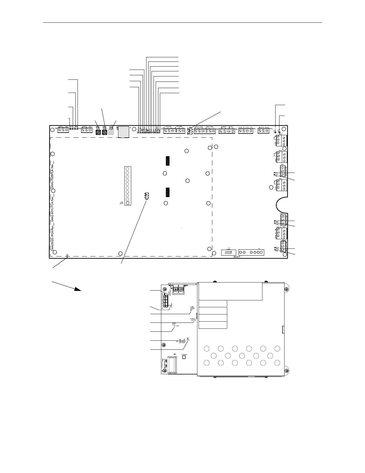
Indicator, Jumper and Switch Locations
Switches and LED indicator locations are illustrated in Figure 2.3.
Figure 2.3 LED Indicator, Jumper and Switch Locations
LED Indicators. Refer to Table 2.3 on page 20
DAP A TX:
LED 19
DAP A RX:
LED 20
DAP B TX:
LED 21
DAP B RX:
LED 22
AL BUS: LED 10
AMP FAIL: LED 4
AUDIO: LED 13
STATUS: LED 25
TRBL: LED 9
SIG SIL: LED 24
AUX: LED 11
FFT: LED 12
RST: LED 23
USB: LED 18
ON1: LED 8
TRBL1: LED 14
SW3:
ONES
SW2:
TENS
SW5:
SIG SIL
2 WIRE/4 WIRE:
SW1
ON2: LED7
TRBL2:
LED 15
ON3: LED 6
TRBL3:
LED 16
ON4: LED 5
TRBL4:
LED17
DA2APCA brd.wmf
CPS24-bboard.wmf
+24V AUX: LED 5
+5V AUX: LED 6
LOGIC POWER: LED 1
TROUBLE: LED 2
EARTH FAULT: LED 3
AC: LED 4
GND FAULT: SW1
BACKUP FAIL: LED 26
RM-1: LED 1
Dotted line indicates position of
the DAA2’s CPS-24 Power
Supply Board
PRIMARY AMP:
SW4
 Loading...