56 DAA2 & DAX — P/N 53265:A1 8/24/2011
DAX Digital Audio Amplifiers DAX Installation
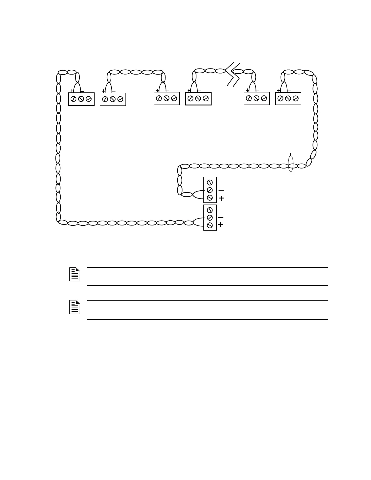
Wire Connections
Figure 3.12 Wire the Digital Audio Loop Connections
Refer to “EARTH FAULT (Switch 5) - DAX-35 Only” on page 65 for information on enabling
earth fault detection on the wire DAL.
Fiber and Wire/Fiber Connections
DAX boards are wire, but may be converted partially or fully to fiber boards with the use of DS-
FM or DS-SFM fiber option modules. Refer to Section 5, “Fiber Option Modules”, on page 75 for
installation instructions.The fiber, or wire/fiber cabling between these ports provides a Digital
Audio Loop (DAL) for programming; alarm, control, trouble, automatic audio messages, address
and firefighter telephone data; and live voice paging communications.
Figure 3.13 gives an example of how a DAL can be formed using mixed wire and fiber connectors.
TB1
TB2
DAP A
REF
DAP B
REF
DAX #1
Refer to the Wiring Guide, p/n 52916ADD, for acceptable
wire types and associated distances between ports.
Do not splice a cable. Splicing will degrade the signal, and
the recommended distance will no longer apply.
DAX #2 DAX #32
TB1
TB1
TB2
TB2
DVC
DAPA, TB3
DAPB, TB2
REF
Optional Style 7 return
Connections are polarity
sensitive.
Connections are port
sensitive. Always connect
Port A to Port B.
REF
DAP A
REF
DAP B
REF
DAP A
REF
DAP B
REF
NOTE: Digital Audio Ports A and B must be wired in Style 4 or Style 7 configuration. Do not wire
them in bus configuration.
NOTE: Style 4 configuration must be installed in accordance with the requirements for
survivability from attack by fire in the National Fire Alarm Code, NFPA 72.
 Loading...